
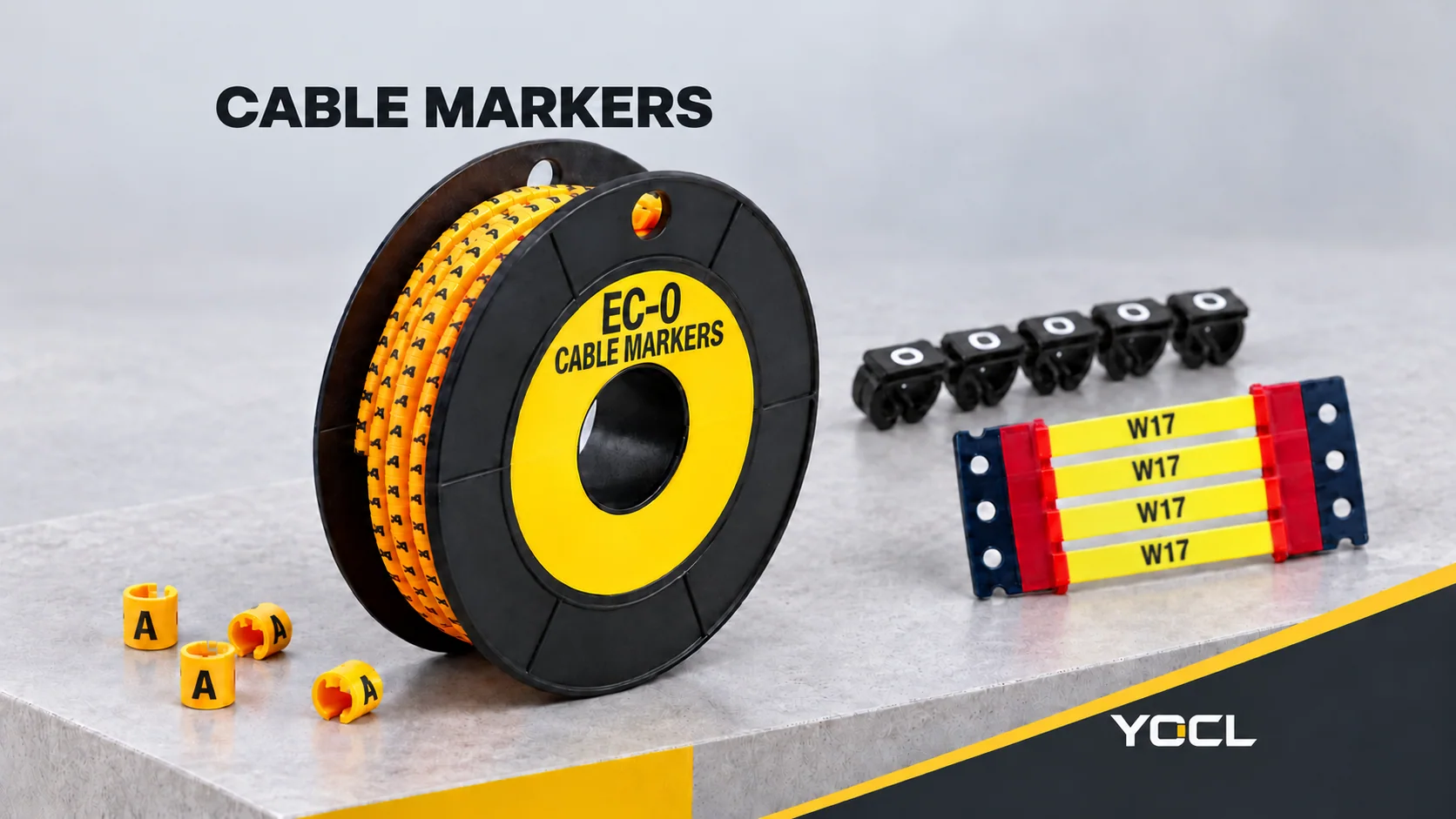
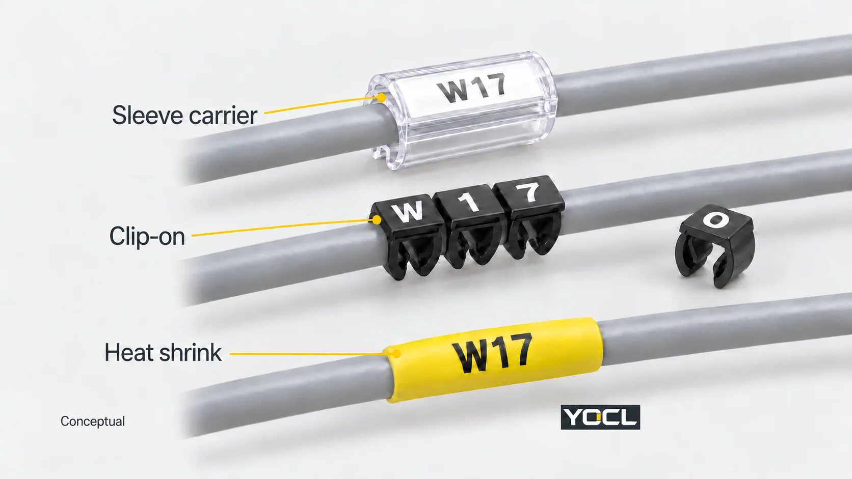
Cable markers carry identifiers on wires and cables so physical wiring can be matched to drawings, schedules and equipment records. Sleeves carry characters or inserts, clip-on markers attach individual characters from the side, and heat-shrink labels recover around the cable. The useful distinction is how the marker fits, when it can be fitted and what information it carries.
Wire markers identify a conductor or cable; they do not make its electrical connection, secure a bundle or establish an insulation rating. The public scope of IEC 62491:2008 places industrial cable and core labelling in this documentation-to-equipment relationship.
Three Formats, Three Ways to Carry the Legend
| Format | What carries the identification? | First question to resolve |
|---|---|---|
| Marker sleeves and carriers | Individual sleeve characters, or an insert held by a sleeve/carrier | Does the selected profile fit the insulated wire, and how is it fitted? |
| Clip-on characters | Separate numbered, lettered or symbol-bearing clips | Can the open profile seat on this wire at the available location? |
| Heat-shrink labels | A printed legend on a recoverable sleeve | Can it pass onto the cable, recover to the required fit and be processed with the specified printing system? |
The names overlap: a heat-shrink label is also a sleeve. Here, “sleeves” means non-shrinking characters or carriers, while “heat shrink” identifies the recoverable construction. This distinction prevents ordering an ordinary marker sleeve when the job calls for a printed shrink label.
Sleeves: Individual Characters or an Insert
Individual characters build a code one piece at a time. YOCL’s EC PVC cable markers use soft polyvinyl chloride (PVC) with a flexible concave inner profile. The range lists digits, uppercase letters, symbols and blanks. A multi-character identifier therefore requires a character schedule as well as a marker-size selection.
Other sleeves carry a separate insert. The exterior reference for YOCL’s 201–205 marker sleeves shows a transparent carrier with a longitudinal opening and an identification surface. Its product table separately specifies conductor area, recommended cable diameter and maximum diameter.
Do not infer the fitting method from “sleeve” alone. A closed slide-on sleeve needs cable-end access; an open carrier has different geometry. Confirm the selected model’s fitting method and insert compatibility before planning it into an already wired assembly.
Clip-On Characters: Side Entry to the Wire
YOCL’s SM clip-on markers use rigid polyoxymethylene (POM). Their open-legged profile permits fitting after cable installation. Numbers, letters and symbols can be assembled into a short code on the wire.
This makes side access useful when an existing termination obstructs a closed sleeve. It still needs space around the wire and the correct marker size. A clip that can reach the wire is not necessarily a clip that seats properly on its jacket. Check the actual fit rather than assuming the same conductor area guarantees retention.
Heat-Shrink Labels: One Printed Sleeve
A heat-shrink marker carries the legend on a sleeve that contracts under its specified heating process. A complete identifier can be printed on one piece instead of assembled from individual characters.
YOCL’s halogen-free heat-shrink cable markers use this sleeve format. For an ordinary closed sleeve, plan end access and position it before a termination prevents threading it onto the cable. Confirm the permitted cable-size range and processing instructions for the actual product.
Printing adds another compatibility question: sleeve dimensions, supply format, printer, ribbon and required print durability must work together. “Printable heat shrink” does not identify a universal printer cartridge or ribbon. For the recovery terminology behind that fit check, see What Is Heat Shrink Tubing?.
Fit the Insulated Wire, Not Just Its Conductor Size
Conductor cross-section is expressed in mm². The diameter of the insulated wire is expressed in mm. These are different measurements: two wires with the same copper area can have different jacket diameters.
The 201–205 sleeve table makes another distinction visible:
| YOCL sleeve model | Recommended conductor area | Recommended cable outside diameter | Separate maximum cable diameter |
|---|---|---|---|
| 201 | 0.25–1.5 mm² | 1.5–3.0 mm | 5.2 mm |
| 202 | 0.5–2.5 mm² | 2.0–4.0 mm | 6.5 mm |
These values come from the 201–205 product table. Its selection guidance explicitly keeps the maximum diameter separate from the recommended fit range.
For an illustrative 0.75 mm² wire with a measured 3.4 mm outside diameter, the conductor area falls within both rows. The diameter falls within model 202’s recommended range but outside model 201’s. Model 201’s 5.2 mm maximum does not turn 3.4 mm into a recommended fit.
This is a table-reading example, not a tested installation. Use the same model row for both measurements, then confirm the sample on the actual wire. For a flat cable, provide width and thickness instead of forcing its shape into a round-wire diameter assumption.
A Wire Identifier Is Different from a Terminal Identifier
Agree what the legend means before choosing characters or printing labels. It may identify a wire, cable, core, circuit or destination under the project’s documentation scheme. Those meanings are not interchangeable.
For example, an illustrative schedule can identify one wire as W17, running from terminal X1:4 to X2:7. Under that scheme, W17 remains the wire identifier at both ends, while the terminal identifiers differ. Printing only “4” on one end and “7” on the other would communicate terminal positions, not the agreed wire ID.
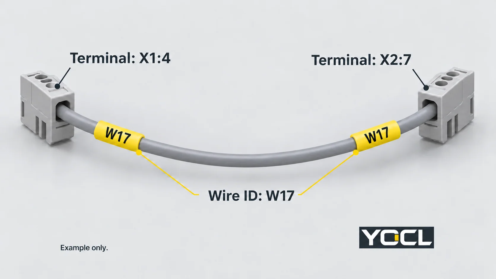
A cable identifier can also refer to an outer multi-core cable, while separate core identifiers distinguish the wires inside it. A label on the outer jacket does not identify every internal core. Likewise, a terminal marker belongs to the terminal assembly; the terminal-block guide explains that accessory context.
Keep project IDs consistent with required conductor-function identification. The public scope of IEC 60445:2021+AMD1:2026 covers equipment-terminal identification and designated conductor identification using colours or alphanumeric notation. A yellow marker carrying W17 is not a substitute for the applicable functional identification scheme. The example above is not a prescribed IEC numbering format.
Readability Depends on the Marker and the Print System
Assess the legend after fitting, not only while it is on a roll or carrier. Check character order, viewing direction, space between adjacent markers and whether the installed wire bend hides the text. For printed sleeves, include a processed sample when confirming the specification.
YOCL’s heat-shrink marker product record declares halogen-free, low-smoke and flame-retardant characteristics and a 125°C rated temperature. It distinguishes that rating from installation heating conditions. Those declarations do not apply to every PVC sleeve or POM clip, and they do not supply a heat-gun setting or a project-specific test certificate.
For safety-related marking evidence, UL Solutions’ marking and labelling program evaluates permanence under specified conditions. Its printing-material category identifies acceptable printing inks within the recognition. This illustrates why label stock and printing material must be assessed together; it does not establish recognition of these YOCL examples or coverage of every non-adhesive marker format.
UL’s program FAQ also separates marking permanence from electrical, flammability and structural ratings. A durable identifier is useful for traceability; it does not establish the electrical duty of the wire or connection beneath it.
Find the Next Document by the Unresolved Question
| Your next question | Relevant information |
|---|---|
| Which format suits available access? | Selected sleeve/carrier or clip model’s fitting information |
| Which size fits this insulated wire? | Exact model’s conductor and cable-dimension table, followed by sample fit |
| Which characters and quantities are needed? | Approved identification schedule and quantities per character or complete legend |
| Can this printer produce the required shrink labels? | Marker supply format, printer/ribbon compatibility and processed sample |
| Will the legend remain readable in service? | Required exposure conditions and applicable marking-system evidence |
Strips, holders and marker boxes provide other identification areas and insert arrangements. Marker cable ties combine a tie with a marking area; they serve bundling as well as identification. These accessories require their own dimensions and fixing checks rather than inheriting a sleeve’s fit.
Use the YOCL cable-marker range to locate the relevant family. For an enquiry, send the wire dimensions, installation stage, model or format, legend schedule, character or label quantities, and any printing or exposure requirements.
Related reading: See heat-shrink cable-end sealing and clip-on, slide-on and heat-shrink marker comparison.
Related reading: marker sizing and sleeve fit.
References
- IEC — IEC 62491:2008, Labelling of cables and cores — public abstract on the relationship between industrial wiring and technical documentation; full standard not consulted.
- YOCL product information — EC PVC Cable Markers — character choices, material and exterior profile.
- YOCL product information — 201–205 Cable Marker Sleeves — exterior reference and separate recommended/maximal fit fields.
- YOCL product information — SM Type Clip-On Cable Markers — material, open profile and post-installation fitting.
- YOCL product information — Halogen-Free Heat Shrink Cable Markers — sleeve format and declared characteristics/temperature.
- IEC — IEC 60445:2021+AMD1:2026, consolidated edition 7.1 — public scope for equipment-terminal and conductor identification; full standard not consulted.
- UL Solutions — Marking and Labeling Systems Program — evaluated permanence, printing-material compatibility and certification scope.
- UL Solutions — Marking and Labeling Systems FAQs — boundary between marking permanence and other ratings.