
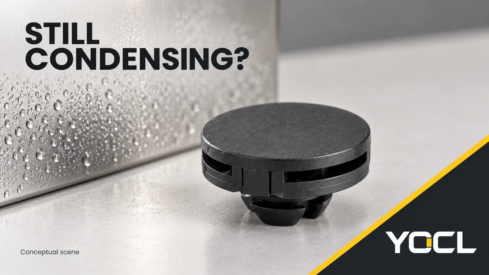
If condensation persists after fitting a vent plug, investigate four possibilities before adding another vent: water entering as liquid, an unsuitable or obstructed breathing installation, moisture remaining inside, and surfaces that still become cold enough to collect droplets. A vent can provide its intended breathing function while the enclosure remains vulnerable to condensation.
Start with safety. If water has reached electrical parts, or there is corrosion, tracking, tripping or other damage, take the equipment out of service through the site’s safe procedure. Internal inspection, fitting removal and sensor installation require competent personnel and an appropriate isolated state. The UK Health and Safety Executive’s HSG85 guidance, particularly pages 20–22, explains dead working, secure isolation and proving dead. This checklist does not replace those procedures.
Key Takeaways
- Record where and when moisture first appears; a wet enclosure alone does not identify its source.
- Confirm that the installed model provides routine breathing, then inspect access to its gas path and its mounting interface separately.
- Use operating-cycle evidence to decide whether the remaining problem concerns water entry, the fitting, internal moisture or cold surfaces.
- Replace a demonstrably damaged or unsuitable component; escalate unresolved enclosure moisture instead of assuming that more airflow will cure it.
Start with the wet pattern and the event that preceded it
Before wiping away the evidence, photograph accessible wet areas when safe to do so. Mark the first observed location, the apparent route and whether there is pooled water. Record recent rain, washdown, lid opening, installation work, shutdown and overnight cooling. If the enclosure is unsafe to access, preserve observations from outside and let the responsible person arrange inspection.
Use the following sequence to choose what to investigate. These patterns are clues: liquid ingress and condensation can coexist, and droplets can move after forming.
| What you observe | Safe check or evidence to request | What the result suggests | Next action |
|---|---|---|---|
| A wet trail begins near the newly fitted vent after rain or washing | After isolation, inspect the perimeter, seating and mounting details against the exact drawing; record external exposure | The retrofit interface or its exposure needs investigation; a trail alone does not prove membrane failure | Have the enclosure/fitting supplier review the interface and specify an appropriate assembled verification |
| Wetness starts near a lid joint, cable entry or conduit | Trace accessible paths and inspect those interfaces under the equipment procedure | Another liquid-entry route remains possible even though a vent is fitted | Correct the confirmed entry issue through the equipment’s approved method |
| Droplets recur on a wall or lid after shutdown or overnight cooling | Obtain local air temperature/humidity and relevant surface temperatures through that period | Cold-surface condensation is a plausible branch | Compare the recorded surface conditions with local dew point before changing the vent |
| A bracket, coating, packing material or deposit covers the vent openings | Compare installed photographs with the product drawing and the accessible loose-part geometry | The intended gas path may be restricted | Restore the approved access arrangement; seek cleaning or replacement instructions where needed |
| Moisture returns after work involving wet parts or a damp interior | Review assembly/service history and inspect accessible contents after isolation | A remaining internal moisture source needs investigation | Remove the identified source and use an equipment-approved drying/recovery procedure |
| The installed part has only a pressure-release specification | Confirm its complete model and documented function | It may not provide the intended routine breathing function | Review a suitable breathing configuration before modifying the enclosure |
For the underlying physics, use why condensation forms inside a sealed electrical enclosure. Here, the practical question is which branch your observations support.
Verify what was fitted, then inspect two separate paths
Confirm the complete model and its function
Compare the order code, supplied part and latest product documentation. A description such as “vent,” a matching thread or a similar-looking cap is insufficient to establish the function. YOCL’s breather and pressure-relief range separates routine breather vents, one-way pressure-relief valves and combined devices. A relief threshold alone does not demonstrate the routine breathing behavior required by the enclosure.
If the function is uncertain, obtain the actual data before changing the layout. The enclosure vent-plug overview maps those functions without turning a relief device into a substitute for a breather.
Inspect access to the intended gas path
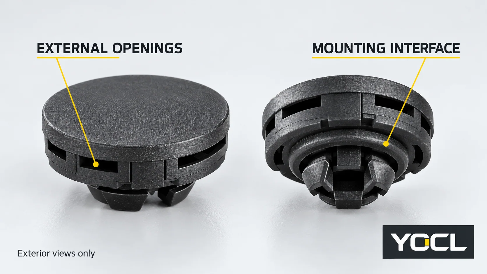
Look at the fitting as installed, including both sides where safely accessible. Check for paint or sealant across openings, retained installation masking, deposits, nearby packaging, brackets and internal components that obstruct access. Compare photographs with the approved layout and exact model information.
This is an access check, not a membrane performance test. A clean-looking exterior cannot establish that the complete vent still meets its specification. Do not puncture the membrane, dismantle the cap, blow compressed air through it or apply an improvised solvent to “prove” flow. Request the model’s maintenance instructions; where approved recovery cannot be established, seek a replacement decision from the supplier.
Inspect the fitting-to-enclosure perimeter separately
The intended breathing path and the mounting perimeter have different jobs. Review the opening, seating surface, seal, retention and surrounding clearance against the actual installation requirements. For a threaded fitting, confirm the specified thread and sealing arrangement. For a snap-on fitting, obtain the permitted opening and panel-thickness requirements.
YOCL’s K-series snap-on product information illustrates why this distinction matters: its body-dimension table explicitly does not establish the mounting-hole tolerance or permitted panel thickness. A part that snaps into an opening has not, by that observation alone, demonstrated a suitable sealed interface.
If cable-entry work accompanied the vent retrofit, review it as a separate possible source. The junction-box cable-entry planning guide explains the surrounding layout questions. Avoid drilling another opening until its effect on the completed enclosure has been reviewed.
If the fitting looks correct, record the cycle that produces moisture
A daytime photograph of a dry enclosure can miss the event that matters. Build a record around the actual recurrence: the first cold night after shutdown, washdown, a wet-weather period or the return to service. Include internal and external conditions, equipment state and any lid opening.
For suspected condensation, correlate internal air temperature and relative humidity with the temperatures of relevant cold surfaces. NPL’s dew-point guidance explains how air temperature and humidity relate to dew point. A surface at or below the local dew point supports the condensation hypothesis; bulk-air temperature alone does not establish that surface condition. Readings near the calculated boundary require attention to measurement uncertainty and sensor location.
Have competent personnel plan measurement locations and install suitable sensors safely. Where an operating record is necessary, use the equipment’s approved monitoring arrangement, with guards and covers restored. Do not leave an electrical enclosure open or route improvised leads through its seal to collect data. Opening the lid also changes the conditions being investigated; record that intervention.
Collect these fields together:
- Time and state: powered, shutdown, restart, rain/washdown and lid opening.
- Moisture observation: first location, wet trail, droplets or pooled water, with photographs where safe.
- Relevant conditions: internal air temperature/humidity, external conditions and selected surface temperatures where measurement is justified.
- Installation identity: exact vent code, mounting details, exposure and any obstruction found.
- Changes made: the confirmed defect, corrective action, date and the conditions used for the next review.
Treat the resulting pattern as evidence for a decision. A cold-surface pattern calls for a moisture/thermal assessment. A localized wet route tied to an external water event calls for an ingress investigation. If both appear, retain both branches rather than declaring a single cause prematurely.
Do not convert a catalogue airflow figure into a drying promise
For example, YOCL lists K01 airflow as at least 800 mL/min at a pressure differential of 70 mbar. That is a declared model-specific test point. It is not the airflow continually available in an installed enclosure, and it gives no guaranteed time to remove internal moisture.
If breathing performance remains a concern after inspecting the fitting, provide the supplier with the enclosure volume, temperature-change profile, exposure and required pressure response. Ask for relevant flow characteristics at the intended conditions and review the complete installed path. Do not extrapolate a single point into an equalization time or assume that doubling the number of vents will halve condensation.
Once the available evidence supports a suitable breathing installation, adding vents is a separate design proposal requiring its own justification. It should not replace investigating the water source and cold surfaces.
Choose the action that matches the evidence
| Finding | Appropriate decision | What still needs verification |
|---|---|---|
| Confirmed obstruction or mounting defect, with otherwise suitable parts | Correct the installation using the documented arrangement | Required breathing access and the completed enclosure’s applicable protection after correction |
| Cracked body, failed retention, damaged seal or damaged membrane where visible without unauthorized dismantling | Obtain a model-approved repair or replacement decision | Cause of damage, compatibility and the restored assembly; replacing the part alone does not close the moisture investigation |
| Contamination with no approved recovery method, or uncertain component condition | Seek supplier assessment and replacement advice | Suitability for the actual exposure; a visually cleaner cap is not evidence of restored performance |
| Suitable vent installation, but a recurring cold-surface pattern remains | Escalate the enclosure’s moisture and thermal design | Appropriate controls for the documented operating cycle; heater, moisture removal or liquid management needs separate design approval |
| Mixed evidence, unexplained recurrence or wet/damaged electrical components | Keep unsafe equipment out of service and escalate to the responsible equipment specialist | Root cause, electrical condition and authorized return-to-service criteria |
Do not drill a drain hole, fit a heater, add desiccant or change the vent location as an undocumented trial. Each changes the system and needs an appropriate design or maintenance decision. Removing visible water is only one part of recovery; the condition of affected electrical equipment also matters.
Close the investigation under comparable conditions
After the confirmed problem has been addressed, repeat observations through the relevant operating and exposure conditions. Use the same documented measurement locations where practical and record differences in weather, load or shutdown duration. A dry result during milder conditions is limited evidence for the original problem.
Have the responsible person define the observation period and acceptance criteria for the application. This article supplies no universal humidity target, drying time or inspection interval. An approved ingress or functional test, where required, should follow the applicable equipment procedure; an improvised hose test or pressure test can damage the assembly and obscure the diagnosis.
For a model review, send the exact vent reference, mounting drawing, photographs and operating-cycle record through the YOCL breather vent range. State whether you need help resolving a component defect, an installation interface or a remaining enclosure moisture problem. That distinction makes the next technical discussion actionable.
References
- UK Health and Safety Executive, Electricity at work: Safe working practices (HSG85), third edition, 2013, pp. 20–22—UK guidance on working dead, secure isolation and proving dead.
- YOCL product information, Breather Vent Plug & Pressure Relief Valve Manufacturer—declared functions and specification boundaries; reviewed November 2, 2026.
- YOCL product information, K-series Snap-on Waterproof Breathable Valve—model airflow conditions, mounting-document limits and original product-image references; reviewed November 2, 2026.
- National Physical Laboratory, How do I convert between dew point and relative humidity?—dew-point interpretation and temperature/humidity relationships.