
Start with an entry schedule: list every cable, its route and outside diameter, then assign each to a permitted enclosure entry. Check the space outside and inside the box, the cable-to-entry seal, the entry-to-enclosure seal, any unused openings and the access needed for assembly and service. Finish with a drawing and a verification plan for the complete installed assembly.
First establish whether the selected box has fixed entries or permits customer modifications. Do not assume a blank wall can be drilled, that an unused entry can be left open, or that separate box and gland ingress protection (IP) markings automatically establish the assembled result.
Planning can be done from drawings, but work on existing electrical equipment requires competent personnel. Before opening or modifying it, identify and isolate all sources, secure against reconnection, address stored energy and verify the work area is dead under the site’s procedure. The UK Health and Safety Executive’s safe working guidance explains isolation and verification; local requirements and the equipment manufacturer’s instructions also apply.
1. Record the Cables and the Exposure
Before choosing entry positions, gather the approved circuit and equipment drawings, cable data, enclosure and entry-fitting documents, environmental requirements and installation constraints. Identify the person responsible for approving changes. Record:
- The number and purpose of cables, including any planned future cable and its required method of closure until use.
- Each cable’s actual outside diameter, construction, destination, approach direction and required bend space from its manufacturer.
- The enclosure model, available or permitted entries, wall construction, mounting orientation and internal components.
- Exposure to rain, washdown, dust, immersion or other conditions, including how water may reach each side of the installed enclosure.
- Space for fittings, tools, cable routing, cover opening, inspection and later maintenance.
A waterproof junction box overview explains the enclosure and its interfaces. Here the task is to turn those interfaces into a usable entry layout for a particular installation.
2. Count and Allocate Permitted Entries
Distinguish a fixed-entry product from an enclosure whose manufacturer expressly permits additional holes. A fixed-entry product may have a predetermined number and arrangement of fittings. For example, YOCL’s F3-3T product page describes three entries. The product image below helps identify locations; it does not establish how those entries must be assigned or confirm a particular assembly’s ingress protection.
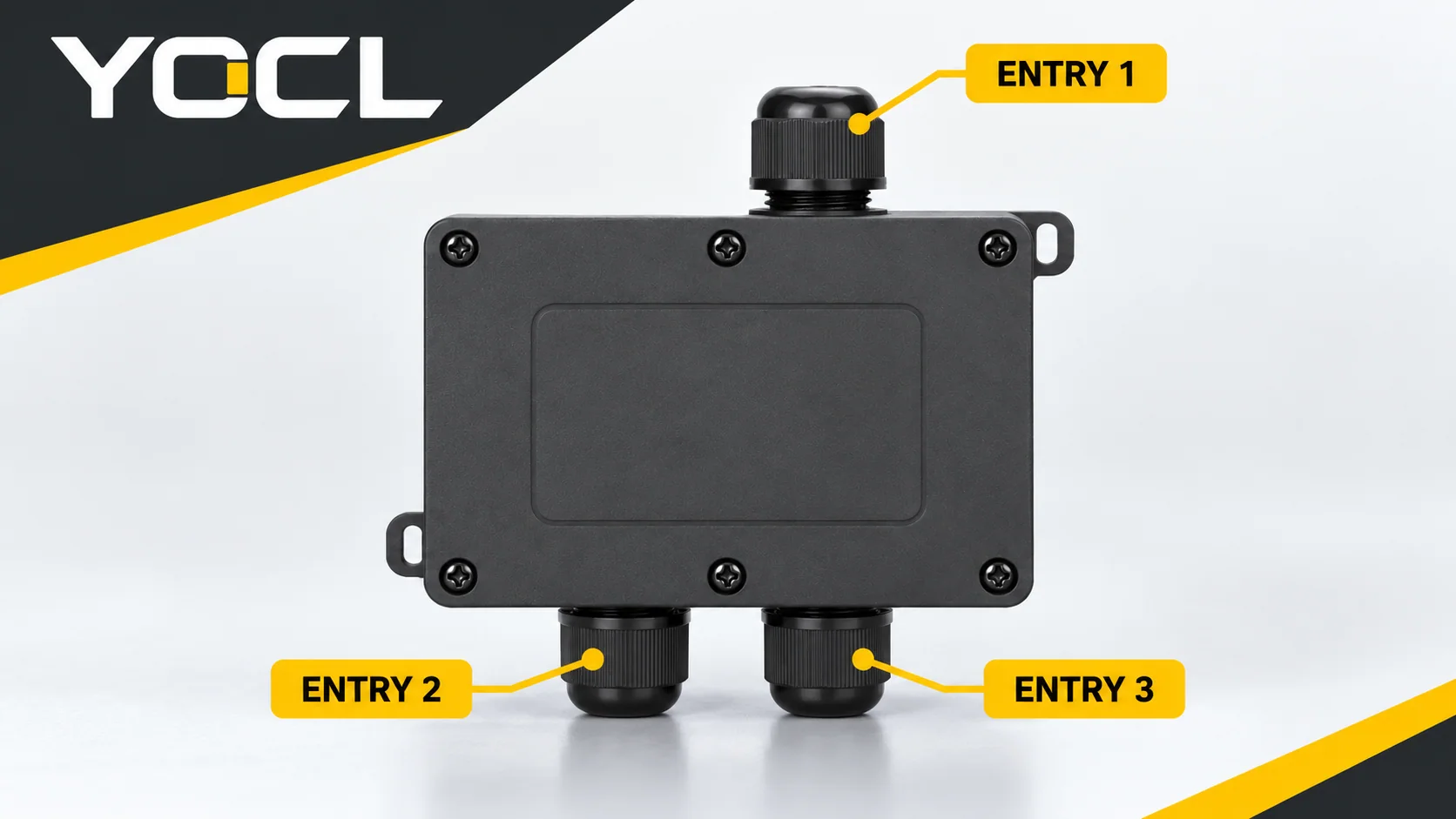
Count the actual cables, not merely the number of connections inside the box. A proposed spare needs a manufacturer-approved closure compatible with that exact entry. If the instructions do not identify a suitable plug or configuration, treat the spare as unresolved and ask the supplier. A cap that looks close or an empty compression fitting is not automatically an approved closure.
For an enclosure intended to be modified, obtain the permitted wall areas, hole and edge requirements, accessory compatibility and any limitations on modification before selecting locations. The enclosure manufacturer and project documents govern whether modification is allowed and how it affects the declared protection. If the necessary information is unavailable, stop the layout review rather than guessing where to drill. Factory-supplied fixed entries should not be treated as a blank enclosure.
3. Map Entry Positions to the Cable Routes
For each cable, draw its approach outside the box and its path to the intended connection inside. A useful layout leaves the entry fitting accessible and avoids forcing the cable to change direction at the seal. Include the space taken by the fitting, locknut or other specified hardware, cover fasteners, partitions and wiring components where applicable. Confirm the cable can be connected, inspected and serviced without damaging the jacket or obstructing the cover.
Check both outside and inside the enclosure. A location that looks convenient from the outside may leave too little room to route a conductor or operate a terminal inside. Likewise, a neat internal route may place the fitting against a wall or cable tray where it cannot be assembled. Use the cable manufacturer’s required bend and handling instructions and the actual component drawings; there is no universal bend radius or entry spacing in this guide.
Consider the installed orientation and exposure, including whether water can collect around an entry, run along a cable toward it or reach it during cleaning. A particular entry direction is not a universal substitute for a suitable seal or exposure assessment. If the cable’s permitted route, fitting access and required environmental performance cannot all be met, revise the position, enclosure or routing before installation.
4. Check Both Sealing Interfaces for Every Entry
A cable entry has at least two planning boundaries: where the fitting meets the cable, and where it meets the enclosure. The applicable details depend on the selected construction. A fixed-entry box can use a different arrangement from a separate threaded cable gland; do not assume their parts are interchangeable.
| Interface | Record and check | Stop if… |
|---|---|---|
| Cable to entry seal | Actual cable outside diameter and shape; seal configuration and permitted range; cable jacket condition and compatibility. | The cable is outside the documented range, the cable surface is unsuitable, or the seal selection is unknown. |
| Entry fitting to enclosure | The specified opening or thread, wall thickness and surface, sealing or locking parts, and assembly instructions for that combination. | The fitting or opening is not documented as compatible, the wall is damaged, or required sealing parts are missing. |
| Unused entry | The designated closure, its compatibility with the entry and the intended exposure. | The correct closure or its installation requirement cannot be confirmed. |
| Cover and enclosure | Cover seal and fasteners, enclosure condition, mounting and access for inspection. | A damaged seal, distortion or blocked cover prevents the prescribed assembly. |
IEC 62444’s public definition describes cable glands as a means of entry that provides sealing and retention; additional functions depend on the design. It does not approve a particular box-and-gland combination. Check any strain-relief, bonding or shielding function against the actual product and assembly instructions.
The cable gland selection guide covers the individual fitting’s cable and thread choices. It does not replace the selected enclosure manufacturer’s requirements.
5. Prepare an Entry Schedule
The following is a blank planning example, not a recommended wiring arrangement. The numbered entries can be adapted to the actual box; all part numbers and dimensions must come from the project and product documents.
| Entry | Cable / purpose | Approach and internal destination | Fitting, seal or closure | Exposure and space check | Status |
|---|---|---|---|---|---|
| 1 | Record cable ID and actual diameter | Record incoming route, bend space and destination | Record exact compatible entry and seal | Record wall, cable and service-access checks | Confirm / revise |
| 2 | Record cable ID and actual diameter | Record route and destination | Record exact compatible entry and seal | Check against entry 1, cover and internal components | Confirm / revise |
| 3 | Record cable ID, or designate a spare | Record route if used | If unused, record the approved closure and instructions | Verify closure and exposure | Confirm / revise |
Add a row for each actual entry and identify the drawing revision. The schedule should allow another person to check the proposed cable against the actual fitting and box without guessing from a photograph. If a cable, enclosure, wall position, fitting or exposure changes, review the affected rows and revise the drawing.
6. Verify the Assembly and Handover
Before work begins, the responsible designer should confirm that every entry, closure, route and required document is identified. During assembly, qualified personnel follow the specific enclosure, fitting and cable instructions; this article does not provide a drilling, wiring or tightening procedure. Record any approved change and inspect the completed assembly against the schedule and the project requirements.
The IP marking on an individual component does not prove the rating of a modified or completed assembly. The required verification depends on the product, intended conditions and project requirements; obtain the relevant evidence and test or inspection procedure from the responsible manufacturer or project authority. IEC 60529’s public preview describes ingress-protection scope and notes that moisture from condensation is a separate matter for the relevant product standard. An entry seal is therefore not, by itself, proof that condensation will be prevented; see condensation in sealed electrical enclosures for that separate issue.
If the actual cable range, closure, permissible opening, installation clearance or verification evidence is unresolved, hold the affected entry for engineering or supplier review. Restore covers and return existing equipment to service only after the required checks are complete and authorized personnel follow the site’s restoration procedure.
For a product enquiry, provide the entry schedule, cable diameters, enclosure layout, exposure and required documentation with the intended YOCL waterproof connection box configuration. Confirm the exact model and compatible entry or closure options before the layout is released.
Related reading: See persistent condensation after vent-plug installation.
Related reading: inline and circular waterproof connections.
References
- UK Health and Safety Executive, Electricity at Work: Safe Working Practices (HSG85), isolation and verification of dead conditions.
- YOCL ELECTRIC, F3-3T Mini Waterproof Junction Box, product information and exterior image reference.
- International Electrotechnical Commission, IEC 62444:2010 public preview, section 3.1, cable gland definition.
- International Electrotechnical Commission, IEC 60529 consolidated edition 2.2 public preview, scope and condensation boundary.