
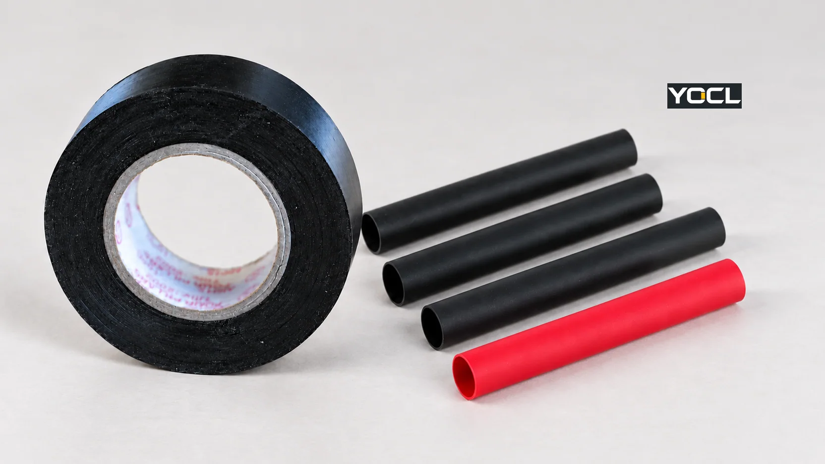
Choose heat shrink tubing when a sleeve can pass over the assembly or be staged before the connection is closed, and the specified components tolerate the installation heat. Choose a specified electrical insulating tape system when the area must be wrapped after assembly or its geometry does not admit a closed sleeve. If moisture exclusion is required, an adhesive-lined sleeve or a purpose-designed wrapping system must be matched to the cable, joint and exposure; a close fit or a few tape turns do not establish a watertight rating. If the connection will be reopened routinely, design an accessible service point instead of treating either covering as a reusable closure.
The choice is about the whole connection, not the familiar appearance of a black wrap or a neatly recovered tube. An electrically sound joint, suitable insulation, environmental protection, strain relief and future access are separate requirements. Neither covering turns a poor splice into an acceptable connection or repairs a damaged cable merely by hiding it.
Decide on the Same Assembly, Not on Material Reputation
Start with the installed joint and its environment. The table compares a conventional, closed heat-shrink sleeve with pressure-sensitive electrical insulating tape. “Tape” here does not automatically include self-fusing rubber, mastic, or a purpose-designed cable-jacket repair kit; those have their own instructions and acceptance criteria.
| Decision question | Heat shrink tubing | Electrical insulating tape | Practical outcome |
|---|---|---|---|
| Can the covering reach the joint? | A closed sleeve must pass over a free end or the largest feature, or be preloaded before a termination or splice is finished. | A wrap can be applied around an accessible area after assembly. | Already closed with no pass-over route: investigate a specified tape or wraparound system; do not force an undersized tube over a connector. |
| What provides insulation? | The selected tube’s electrical properties, recovered dimensions, coverage and complete assembly must suit the use. | The selected tape grade, required build and installation method must suit the use. | Either can be a candidate for a documented joint; material name alone establishes no assembly rating. |
| Is a moisture seal required? | Plain single-wall tubing has no adhesive bond. An adhesive-lined version can form an interface seal when materials, geometry and process are suitable. | Ordinary insulating-tape overlap should not be assumed to form a qualified seal; a specified sealing system may use different tape layers. | Select and verify a sealing assembly, not a visually smooth covering. |
| Will heat affect nearby parts? | Recovery requires controlled heat and clearance around insulation, housings and components. | A pressure-sensitive wrap does not require the heat-shrink operation. | Heat-sensitive assembly: check its limits before selecting tubing. |
| Must the connection be reopened? | A conventional sleeve is normally cut off and replaced; an adhesive liner may bond to the jacket and complicate clean removal. | A wrap can usually be unwound or cut away, then replaced, though adhesive residue and hidden damage still need inspection. | Frequent access: use a designed serviceable connection and cover. |
| Is the underlying splice or cord repair permitted? | Tubing only covers the repair that has already been specified and accepted. | Tape likewise covers only a suitable repair under the applicable rules and product instructions. | Neither is a shortcut around connection, cable-jacket or location requirements. |
These are screening rules, not comparative test results. In some documented assemblies, both materials appear as separate layers with different functions. In others, neither is acceptable. The relevant question is what the selected product and finished assembly can demonstrate under the actual voltage, temperature, exposure, mechanical movement and maintenance plan.
First Establish What the Covering Must Insulate
Heat shrink and tape are insulating products, but the installation is an insulating system. A splice needs an electrically and mechanically suitable connection before a covering is considered. The covering then has to extend over the required conductive area and interfaces, remain where the design expects it, and be suitable for the location. A color, thickness that “feels substantial,” or a successful hand pull does not validate that system.
The public scopes of UL 224 for insulating tubing and UL 510 for insulating tapes show that these are different product categories. They do not make every tube or tape compliant, and their scopes cannot be converted into a single universal voltage or temperature comparison. UL Solutions’ tubing and tape certification explanations distinguish evaluated products and conditions of acceptability. Check the exact product identification, instructions and relevant certification record when the project requires one.
For a new assembly, document the conductor and connection type, maximum operating temperature at the cover, required dielectric and mechanical performance, location, possible fluids or sunlight, and applicable equipment rules. A product may be suitable as internal conductor sleeving yet lack evidence for outdoor exposure or a moving cord. The latter cannot be decided by comparing “heat shrink” with “electrical tape” as generic nouns. In U.S. general-industry applications covered by OSHA 29 CFR 1910.305, conductor insulation must be approved for the voltage, operating temperature and location; rules for splicing flexible cord are more restrictive than “cover the damage.” Other markets and equipment have their own requirements.
If no product instruction or assembly evidence supports the electrical duty, stop at an unverified decision. Adding more layers to an unspecified system is not a way to calculate an acceptable rating.
A Close-Fitting Cover Is Not Necessarily a Moisture Seal
The word waterproof often obscures three different interfaces: the cover over the joint, each end of the cover against the cable jacket, and any branch or step in diameter. A sleeve can look smooth over its center while moisture travels along an unbonded end. A tape wrap can look continuous while its edges, overlaps or substrate prevent the specified seal. Cable flexing, jacket material and surface condition can also change the interface after installation.
Unlined heat shrink: its recovered wall can provide insulation, abrasion protection and a close cover when the chosen product is suitable. Without an inner adhesive, shrinkage alone does not establish a bonded environmental barrier. The distinction is material to the decision: YOCL’s single-wall and dual-wall comparison explains the two constructions in detail. An unlined sleeve can still be the right answer inside a protected enclosure when a seal is not part of its job.
Adhesive-lined heat shrink: the inner hot-melt layer softens during recovery and can bond at the cable interface. It is a sealing candidate if the selected size passes the largest feature yet recovers appropriately on the smaller jacket, the adhesive is compatible with the surfaces, the heat process reaches the required state, and the finished assembly meets its environmental test or project specification. A NASA Kennedy Space Center cable-repair specification illustrates this mechanism in a specific scheme: it calls for adhesive-lined sleeving, surface preparation and installation according to manufacturer instructions. That example is not a blanket approval for every sleeve or exposure (KSC-E-165 Rev F, §§3.11.7–3.11.8).
Electrical insulating tape: a listed or otherwise specified tape may be appropriate for an insulating wrap on a joint. Its pressure-sensitive overlap, by itself, is not proof of a water barrier. A design that calls for moisture sealing may require a designated sealing tape, mastic or layered repair system with prescribed substrate preparation and wrap method. In the same KSC specification, purpose-built cable-jacket repair tape is distinct from ordinary vinyl tape; that distinction matters when someone proposes “just use electrical tape” on a wet or damaged cable.
No visual inspection can establish an ingress-protection (IP) rating for the repaired assembly. Specify the actual exposure and acceptance test where sealing matters. If the location requires a rated enclosure, sealed connector or approved cable repair, use that system rather than assigning the duty to a piece of sleeve or tape without evidence. YOCL’s heat-shrink tubing range likewise makes no universal waterproof or IP claim for its family.
The Installation Sequence Determines Which Method Is Even Possible
The most useful comparison begins before the splice is made. A closed tube must physically travel to the final position. On a cable with a bulky connector already attached at both ends, a tube sized to recover tightly on the cable may not clear the connector; a tube that clears the connector may not recover sufficiently on the cable. The larger pass-over dimension and smaller final diameter both matter. YOCL’s heat-shrink tubing size chart helps compare the supplied and recovered bores from the same size row, rather than choosing by shrink ratio alone.
| Stage | Closed heat-shrink sleeve | Tape or a specified wraparound system | Hold point |
|---|---|---|---|
| Before the joint is closed | Stage the sleeve on an open cable end, clear of the joining operation; verify it will later cover the complete target area. | No preloading is needed, but the final joint must leave enough access for the specified wrap. | Check whether the connector, terminal or branch will block a sleeve later. |
| After the joint is made | Move the sleeve into place, then apply the product’s controlled recovery process without damaging nearby parts. | Apply the chosen tape system by its own instructions, around a stable and accessible substrate. | Do not cover a joint before its required electrical/mechanical inspection. |
| During later inspection or repair | Remove the old sleeve and install a new one; rejoining may be necessary if no free end remains for a replacement closed sleeve. | Remove the old wrap and prepare a new specified covering after the connection has been inspected or remade. | Plan for full removal and renewed acceptance, not automatic reuse of the old covering. |
NASA’s harness-workmanship standard describes the two dimensional checks for a heat-shrink sleeve—large enough before recovery to pass the largest part, and small enough after recovery for the final grip—and warns that nearby heat-sensitive materials must be protected during shrinking. Its workmanship rules apply to NASA harnesses; the transferable engineering point is to check the actual assembly and selected manufacturer’s instructions (NASA-STD-8739.4A, §§9.8–9.11). The KSC repair specification separately describes slipping a sleeve over a cable end before closing a splice. Neither document supplies a universal tube size, heat setting or tape-wrap count for this article.
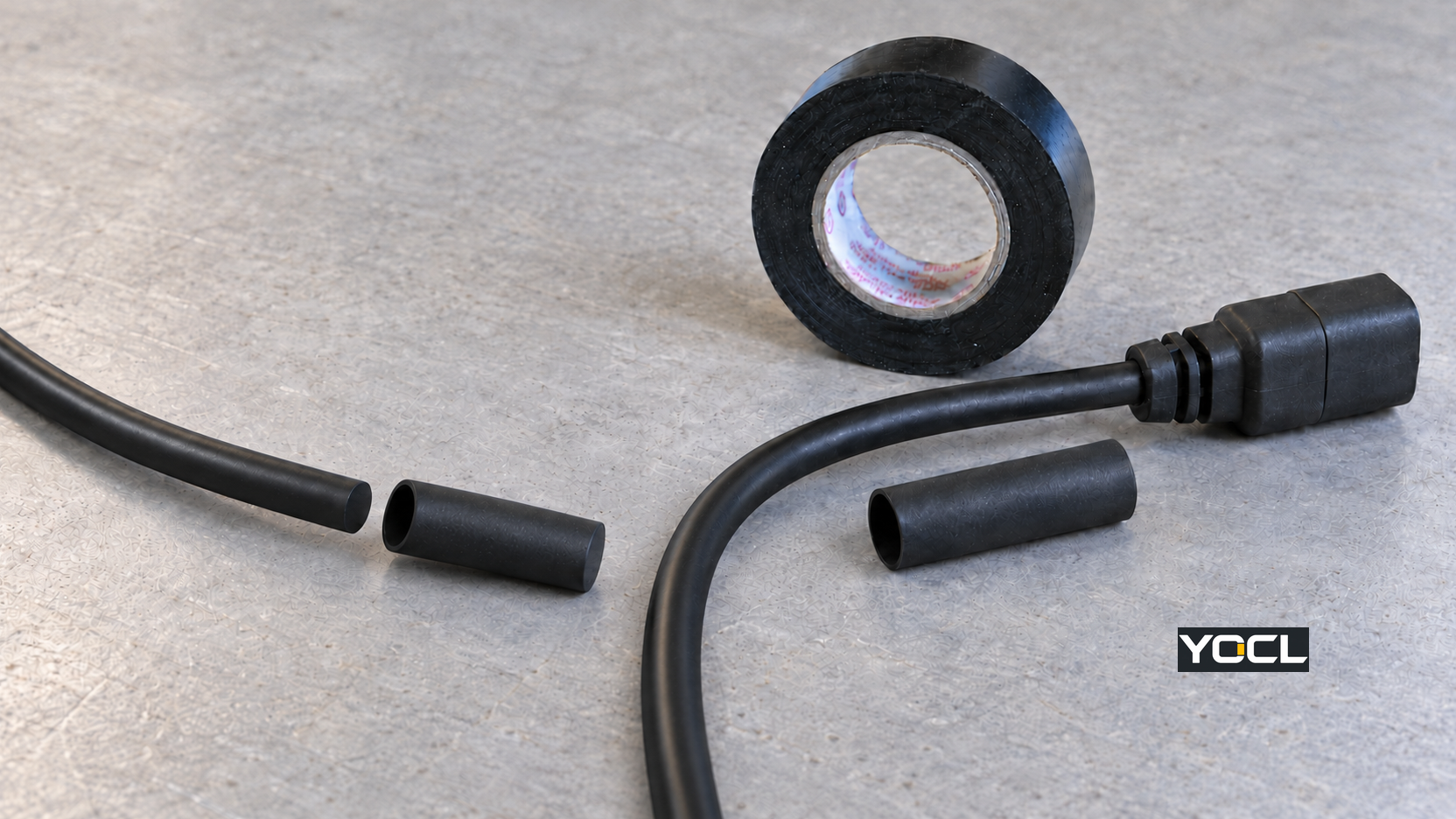
If a sleeve cannot be staged and the project still requires the properties of heat-shrink material, investigate an approved wraparound or split repair product for that application. Do not slit a conventional closed tube and expect it to behave like its original tested construction. Where heat is unsuitable near molded housings, electronics or sensitive jacket materials, tape may be easier to install, but “no heat” only answers the process constraint; it does not prove the tape’s electrical or environmental suitability.
For a detailed procedure once a tubing product has been selected, use YOCL’s cable-splice heat-shrink guide. This comparison stops at the decision and its acceptance checks rather than prescribing a universal heating or wrapping recipe.
Repair Access Has a Cost in Every Option
“Removable” is relative. A technician can usually unwind or cut away a pressure-sensitive wrap without first accessing the cable end, but adhesive can remain on the jacket. Old layers may hide a nick, corrosion, an overheated joint or a loose connection. If the covering was part of a qualified repair system, removing it also ends that assembly’s acceptance; the new installation must follow the applicable instructions and inspection plan.
An unlined heat-shrink sleeve can usually be cut away, but the blade must not score the underlying insulation. The removed sleeve is not reused. With an adhesive-lined sleeve, the adhesive can bond to the jacket, making clean removal harder and potentially requiring more controlled rework or component replacement. The replacement closed sleeve may be impossible to install without opening one end of the connection. These are consequences of the geometry and adhesive interface, not a measured claim that every tape repair is faster than every sleeve repair.
For equipment that is opened repeatedly for testing, diagnostics or field replacement, the strongest design choice is often to move the service boundary: a suitable accessible connector, terminal, enclosure or replaceable subassembly can make the connection inspectable without sacrificing a one-time environmental seal each visit. The required access and protection should be specified together. Routine service also means working under the applicable isolation procedure; U.S. workplace rules in OSHA 29 CFR 1910.333 address de-energization, lockout/tagout and verification for covered electrical work. Repair access is never an invitation to peel a live covering away.
Where YOCL’s Tubing Fits the Decision
YOCL’s catalogue provides two construction routes that should not be conflated with one generic “heat shrink” result. The HTS 2:1 single-wall series is an unlined sleeve for wire and component covering. The HS3X 3:1 and HS4X 4:1 dual-wall series add a hot-melt liner and are candidates when an interface seal and a larger diameter transition are part of the requirement. The ratio alone does not prove fit or sealing; compare the supplied inner diameter, maximum recovered inner diameter, wall/adhesive dimensions and actual cable geometry from the applicable product row. These are YOCL catalogue descriptions, not an independent test of this article’s hypothetical assemblies.
Choose HTS when a suitable unlined insulating cover is all the assembly requires. Shortlist an adhesive-lined series when the end interfaces must be sealed and the cable jacket, process and application can be validated. If no closed sleeve can reach the joint, the catalogued tubing cannot solve that geometry by being chosen in a different color or ratio. YOCL supplies the tubing options here; the tape comparison is an engineering decision aid, not a claim that YOCL sells the tape.
Apply the Decision to Five Common Jobs
Protected in-line splice with an open cable end. If the splice itself is approved and there is room to preload a sleeve, a suitable unlined tube can provide a defined cover when the location needs insulation but no environmental seal. If a seal is specified, evaluate a compatible adhesive-lined tube and the finished assembly. A tape system remains an option only when its documented use fits the same duty; “tubing is always better” would ignore project evidence and access needs.
Connector already fitted at both ends. A conventional sleeve may have no installation route. A specified tape or wraparound system can reach the exposed area after assembly, provided the substrate is accessible and the selected system covers the electrical and environmental requirements. If the required seal has no supported wraparound option, the right response may be to disassemble, change the connector layout or replace the cable—not to stretch a small sleeve over a large connector.
Branch, step or multi-cable exit exposed to moisture. The geometry creates several end interfaces, including spaces between individual cables. An adhesive-lined sleeve may help only if its liner can wet and bond to each relevant surface with the prescribed process; a photograph of adhesive at the end cannot verify that. Ordinary tape overlap is equally insufficient evidence. Specify a branch-rated sealing component or tested repair assembly where the interface cannot be qualified with a simple sleeve or wrap.
Connection opened every service visit. A covering that must be cut away and rebuilt each time may drive inspection errors and extra downtime. Establish whether a serviceable connector or enclosure can carry the access function while the fixed cable run retains its required insulation and sealing. If a removable tape covering is intentionally part of the design, document the product and replacement method; do not assume the removed layers can be reapplied.
Damaged flexible cord or compromised cable jacket. Treat this as a cable-repair and application-rule question first. In covered U.S. general-industry work, OSHA’s flexible-cord rules specify when splicing is permitted and require the repaired cord’s insulation, outer sheath and usage characteristics to be retained (29 CFR 1910.305(g)). A heat-shrink sleeve or tape applied over visible damage alone does not establish those conditions. Use a documented repair or replace the cord as the governing rules and manufacturer instructions require.
What to Record Before Specifying the Cover
The decision is ready for purchasing or a work instruction only when the documents and assembly checks match the proposed duty. Record these inputs together, rather than a material name alone:
- Connection and location: conductor and joint construction, service voltage and temperature, movement, abrasion, chemical or sunlight exposure, and whether immersion or moisture ingress is a stated requirement.
- Installation route: largest feature to pass, final cable diameter, available cover length, whether a sleeve can be staged before closure, and whether controlled heat is allowed near all adjacent parts.
- Selected product and method: exact tube model and size row or exact tape/sealing-system designation, applicable installation instructions, and any documented certification or project acceptance condition. Do not copy a rating from a product category onto the chosen assembly.
- End-interface and rework plan: jacket material, branches and steps, seal verification method if needed, inspection point before covering, expected opening frequency, and how the old covering will be removed and replaced.
- Disposition: mark the solution documented when the parts, process and required assembly acceptance are supported; conditional when a specific fit, compatibility or test result is still needed; reject when no permitted repair or suitable covering system exists.
For a tubing shortlist, send YOCL the cable and connector dimensions, required insulation and sealing duty, jacket material, exposure, and assembly process through the heat-shrink tubing product range. That information distinguishes an unlined cover from an adhesive-lined sealing candidate and makes a size-row discussion possible. If a previously installed sleeve has split or appears not to seal, the failure-diagnosis guide addresses that separate problem.
References
- UL Standards & Engagement, ANSI/UL 224, Extruded Insulating Tubing, 8th edition (2026), public scope preview.
- UL Standards & Engagement, ANSI/CAN/UL 510, Polyvinyl Chloride, Polyethylene, and Rubber Insulating Tape, 10th edition (2020; revised 2024), public scope preview.
- UL Solutions, Insulating Tubing Testing and Certification; tubing categories and conditions of acceptability.
- UL Solutions, Insulating Tape Testing and Certification; tape categories and conditions of acceptability.
- Occupational Safety and Health Administration, 29 CFR 1910.305, Wiring methods, components, and equipment for general use; U.S. general-industry insulation and flexible-cord requirements.
- NASA Kennedy Space Center, KSC-E-165 Rev F (2021), §§3.11.7–3.11.8; a specified cable-jacket and splice-repair scheme.
- YOCL ELECTRIC, Heat Shrink Tubing Manufacturer; catalogue construction, sizing guidance and product-family claim boundaries.
- NASA, NASA-STD-8739.4A, Crimping, Interconnecting Cables, Harnesses, and Wiring (2016), §§9.8–9.11; harness sleeving workmanship.
- Occupational Safety and Health Administration, 29 CFR 1910.333, Selection and use of work practices; U.S. workplace electrical servicing.
- YOCL ELECTRIC, HTS 2:1 Single-Wall Heat Shrink Tubing; unlined construction and model information.
- YOCL ELECTRIC, HS3X 3:1 Dual-Wall Adhesive-Lined Heat Shrink Tubing; adhesive-lined construction and size table.
- YOCL ELECTRIC, HS4X 4:1 Dual-Wall Adhesive-Lined Heat Shrink Tubing; adhesive-lined construction and size table.