
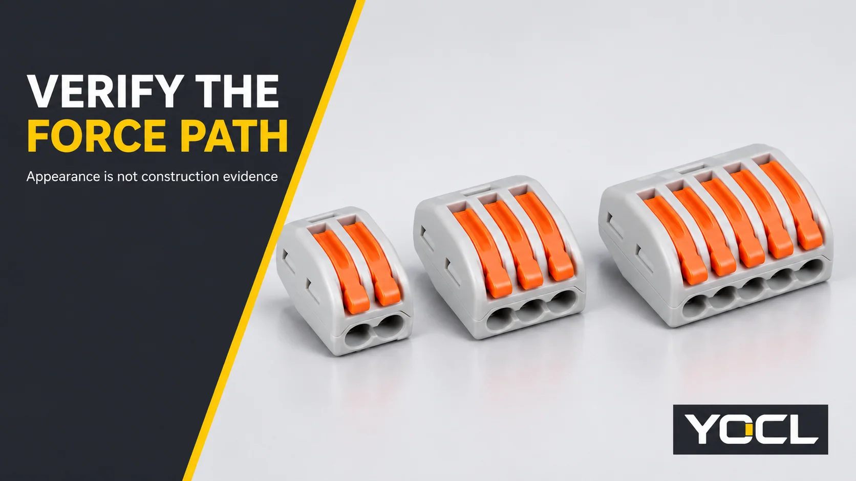
Yes, some lever connectors can loosen as heat accelerates deformation in the structure maintaining contact pressure. When checking fake lever wire connectors, look beyond the lever colour: trace what supplies the force, what carries current, and what keeps those parts together. A self-contained metal clamp and a clamp relying on an inadequately supported plastic wall can look similar from outside. They need different levels of scrutiny before installation.
| Quick screen | Useful evidence | Reason to hold the purchase |
|---|---|---|
| Force path | Exact-model construction drawing and material declaration | No explanation of what maintains contact pressure |
| Identity | Traceable maker, model and matching documents | Listing, package and paperwork describe different products |
| Sample consistency | Uninstalled samples match the documented construction | Loose retention, inconsistent operation or unexplained substitutions |
These checks screen risk; they do not certify a connector. “Fake” concerns false identity, while an undocumented or poorly engineered copy raises a construction problem. An independently branded connector is not counterfeit merely because it has levers. Neither a familiar silhouette nor a favourable sample proves authenticity or long-term suitability.
How lost clamping force becomes a heating problem
A connector needs sustained pressure between the conductor and its contact surface. Closing the lever establishes an initial condition; the important question is whether the structure can preserve that condition through its intended service.
Teardown reporting published by Hackaday describes market samples whose conductor retention depends partly on plastic mouldings, with heating accelerating deterioration. These are reported sample findings, not YOCL tests or a verdict on every similar-looking connector. They identify a failure path worth checking, not a universal failure temperature or lifetime.
The sequence is straightforward:
- A loaded plastic feature deforms. The feature that reacts the clamp load gradually changes shape under sustained mechanical stress.
- The clamp loses preload. Movement at that support reduces the pressure originally established on the conductor.
- The contact becomes more resistive. A deteriorating interface can restrict effective metal-to-metal contact.
- Local heating increases. At the same current, increased connection resistance means more heat at that interface.
- The damage reinforces itself. Additional heat can accelerate deformation, further weakening retention and potentially ending in intermittent contact, arcing or heat-damaged insulation.
Plastic need not visibly melt before this process matters. Creep is deformation under sustained stress; stress relaxation is declining stress under maintained deformation. The Open University’s introduction to polymers explains these time-dependent behaviours and their relationship to temperature. The actual rate depends on the material, geometry and conditions; a generic diagram cannot establish it.
Look for the vulnerable mechanical dependency before looking for scorch marks. A cool, newly assembled sample may conceal that dependency, while a damaged connector no longer reveals exactly how the problem began. No safe-service conclusion follows from an absence of visible melting.
Anatomy of a separate spring-and-busbar design
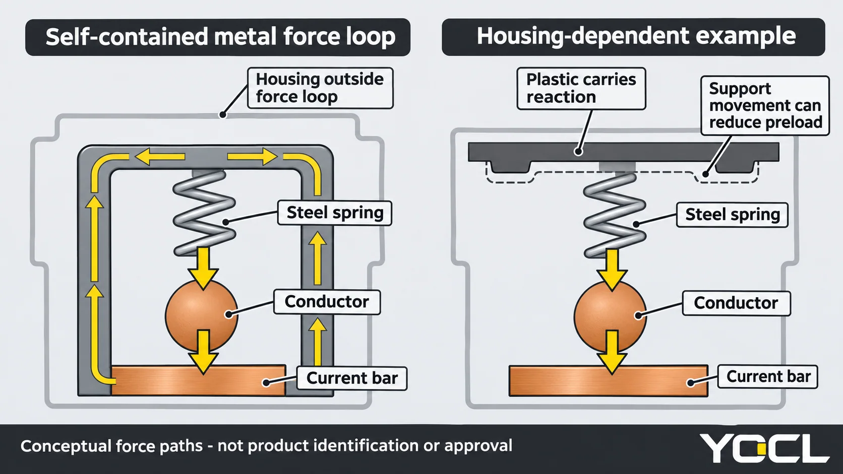
A documented reference is WAGO’s CAGE CLAMP construction: a chrome-nickel spring-steel element and a separate electrolytic-copper current bar with a tin surface. Its published technology brochure describes a self-contained contact unit that does not transfer clamping load to the insulating housing. This is a reference principle, not a description of YOCL internals or a requirement that every acceptable connector use identical construction.
The functional chain is spring → conductor → current bar, with the reaction contained by the metal assembly. Elastic deflection supplies the pressure; the bar provides the intended current path. The spring can accommodate the permitted conductor geometry without asking a plastic wall to preserve the working preload. Separation of functions does not mean the parts are thermally isolated or immune to misuse.
The manufacturer’s material specifications also distinguish contact and spring materials. Together with the brochure, they explain how pressure embeds the conductor at the tin-coated interface to establish a locally gas-tight contact. That describes the contact zone, not a waterproof housing or an approval of an unspecified splice.
The practical lesson is to ask for a force-path explanation, not simply a claim that the connector “has a spring.” A metal piece visible through an opening may be an actuator, retainer or contact. Its presence alone does not show which component supplies lasting force.
Structures that deserve closer examination
A plastic feature completes the clamping loop
In the concerning pattern, a spring or contact bears on a plastic rib, wall or support whose movement directly reduces conductor pressure. Plastic is doing a sustained mechanical job within the working clamp loop, rather than simply surrounding the contact assembly.
Do not confuse that with any plastic near a terminal. An insulating housing can locate components and transmit lever-operating forces without being the element that preserves closed-contact preload. Ask what happens to conductor pressure if the relevant support creeps. A drawing that separates the operating mechanism from the retained-force path is more useful than a general statement about a heat-resistant enclosure.
A formed strip combines spring and current functions
Another construction question arises when the same stamping both carries current and supplies elasticity. Heating and mechanical behaviour are then coupled in that member. An unsuitable alloy, temper or geometry can lose the spring properties needed to retain contact pressure.
However, a single-piece contact is not automatically fake or unsafe. The Copper Development Association’s connector-alloy design guide explains why copper alloys are used for connector springs and contacts: designers balance conductivity, strength, formability and stress-relaxation resistance. It would be incorrect to claim that a current-carrying strip cannot be a spring.
For an undocumented combined-function stamping, request the material specification and the evidence that the complete contact retains force in its declared conditions. Do not infer an alloy from colour or a shiny coating. The buyer’s unresolved question is qualification, not whether every accepted contact must contain a separate steel component.
Cosmetic copying hides the missing information
A copied lever shape, translucent shell or familiar-looking mark can reproduce what buyers recognise without revealing the load path. Conversely, a different colour does not establish different performance. Exterior resemblance is a reason to verify identity, not evidence of either guilt or approval.
Keep the identity and engineering questions separate. Authenticity requires traceability to the claimed maker; construction suitability requires model-specific documentation and relevant verification. Passing one question does not silently answer the other.
Identification checklist for fake lever wire connectors
Use these checks on uninstalled, de-energized samples and their matching paperwork. Record the sample identity so that observations remain tied to the batch being considered. The checks are screening tools, not a substitute for the manufacturer’s prescribed tests.
Check the complete force path
Reassuring evidence: a legible drawing identifies the spring member, contact bar, materials and reaction path. For a claimed separate spring-and-bar design, the documents show both parts and how the metal assembly closes the load loop.
Warning: a supplier sends only an exterior rendering, substitutes a drawing from another model, or cannot identify the element maintaining pressure. If construction cannot be established, record it as unverified and hold the application. Missing disclosure is not proof of counterfeiting, but it prevents the requested structural check.
Identify the housing’s actual role
Reassuring evidence: a documented section or a competent examination of a sacrificial sample explains how the clamp works, including which parts react the retained load.
Warning: the sample differs from the drawing, or an unsupported plastic feature appears essential to maintaining conductor pressure. A translucent housing may still conceal that relationship. Do not pry open an installed connector to investigate; disassembled samples are inspection specimens and must not return to service. One teardown also cannot represent every item in a shipment.
Match markings to the exact documents
Reassuring evidence: maker and model identification on the product and package can be reconciled with the datasheet, conductor entries and applicable documents. Moulded identifiers can help establish consistency, but the complete traceability record matters more than the marking method alone.
Warning: an unexplained logo, inconsistent model names, a standard named without a model-specific record, or a certificate that belongs to another holder or product. Check any supplied certificate with its issuer and match the covered model and scope. Printing is not inherently invalid, and a moulded mark can also be copied. Neither is a shortcut around document verification.
Compare lever and spring operation across poles
Reassuring evidence: equivalent poles in the same documented model operate consistently, with a definite, repeatable spring action under the intended operation.
Warning: unexplained differences between comparable poles, sticking, damaged parts or a lever that does not complete its prescribed movement. Check with the intended conductor and preparation, following the instructions. Finger feel is a way to spot inconsistency; it does not measure retained contact force or establish performance after ageing. Do not bend levers beyond their operating travel to make the test more demanding.
Check conductor retention on a sample joint
Reassuring evidence: the permitted conductor is correctly prepared, fully inserted and retained during the manufacturer’s prescribed installation check. Release it as instructed and examine the contact area for consistent engagement and unexpected strand damage.
Warning: a conductor slips out, is captured only by insulation, or shows unexplained differences from comparable sample joints. A firm hand pull can expose gross retention problems, but it is not a calibrated pull-out test. An even-looking clamp mark cannot prove gas-tightness, thermal stability or authenticity. Do not invent a universal pull force or turn a successful tug into permission for concealed installation.
Use weight and price as prompts, not verdicts
Reassuring evidence: samples are consistent with the verified construction, documented parts and comparable units of the same model.
Warning: an unexpectedly light unit, obvious missing metal or a large unexplained departure from the established product prompts further inspection. Compare like-for-like models; pole count and enclosure size naturally change mass. Price and weight cannot identify a copper alloy, establish spring quality or prove counterfeiting. There is no universal cheap-price or low-weight threshold that turns these observations into a pass/fail test.
The strongest screening record combines documentation, identity checks and sample observations. The weakest record is a bag of similar-looking connectors accompanied only by a low price and a photograph. Write down unresolved questions rather than converting an attractive appearance into a performance claim.
What to do when construction cannot be verified
Quarantine undocumented stock from permanent or hidden installations while the questions remain unresolved. Request a drawing, material declaration, intended conductor information and model-specific test or certification evidence. Ask the supplier to identify which document answers each missing question; another sales image does not close a technical gap.
For a proposed bulk purchase, arrange competent examination of an uninstalled sacrificial sample before committing it to the application. Keep its packaging and batch identification with the observations. Compare supplied stock against the accepted sample and documents, while recognising that a sample teardown cannot establish the consistency of every unit. A visual examination cannot identify alloy composition or replace relevant electrical and mechanical testing.
Teardown reporting also raises possible insurance consequences of undocumented connectors; that is a warning to retain verifiable product records, not a finding that an insurer will automatically reject a claim. Coverage depends on the policy and circumstances. It should not be used to label a seller or to turn a sourcing decision into a legal conclusion.
If an existing installation shows looseness, discoloration or heat damage, have a qualified person assess it under safe isolation. This article’s sample checks are not instructions to open live equipment, deliberately heat an installed connection or continue using a suspect joint until it fails.
What YOCL’s published information does and does not establish
The YOCL 222-41x product page identifies the following catalogue information. These declarations help match an enquiry to the exact product; they are not findings from a teardown or independent tests.
| Published field | Declared information |
|---|---|
| Models | 222-412 / 222-413 / 222-415 |
| Rated voltage and current | 400 V / 32 A |
| Withstand voltage | 4 kV |
| Ambient temperature | -40°C to +105°C |
| Strip length | 9–10 mm |
| Conductor entry coded s+f-st | 0.08–2.5 mm² |
| Conductor entry coded f-st | 0.08–4 mm² |
| Catalogue reference standard | IEC |
Keep the conductor codes with their corresponding ranges; ask for confirmation of the intended wire construction instead of treating a family maximum as permission for every wire.
YOCL’s public page does not declare the spring alloy, current-bar material, housing material or internal force path. This article makes no claim that its connectors use the reference construction described above. Before specifying an application that depends on those details, request the exact model’s material and construction documents. “Catalogue reference standard: IEC” is not a declaration of product certification, and no certification is inferred here.
The wire connector hub explains the wider terminology. The lever-versus-push-in comparison owns the separate operating-method choice; aluminum-conductor admission is another model-specific question. Use the wire connectors category to identify the product requiring documentation, rather than treating it as a list of structurally verified alternatives.
Application overload is a separate failure with a different corrective assessment; this article does not determine suitability for a continuous-load appliance circuit.
FAQ
Does an orange lever prove a connector is genuine?
No. Lever colour and housing shape are exterior features. Authenticity depends on traceability to the claimed manufacturer, while construction and application suitability need their own model-specific evidence. Matching appearance alone answers none of those questions.
Does every single-piece contact loosen with heat?
No. Suitable copper-alloy contacts can provide both electrical conduction and spring action. Ask for the exact material, geometry and qualification evidence. An undocumented bent strip deserves investigation, but its part count alone does not establish failure or fraud.
Is a hand-pull check enough before permanent installation?
No. It may reveal poor insertion or gross retention problems, but it cannot establish long-term force retention, contact resistance, insulation performance or authenticity. Complete the exact-model documentation and application checks; do not substitute an improvised sample test for the required evidence.
References
- Hackaday, Teardown of Dangerous Fake Wago Connectors, attributed reporting of market-sample examinations; not YOCL test data.
- The Open University, Introduction to Polymers, creep, stress relaxation and temperature dependence.
- WAGO, CAGE CLAMP Technology, published reference construction and contact principles.
- WAGO, Material Specifications, material roles; the inspected document is dated May 2022, not a YOCL specification.
- Copper Development Association, Selection of Copper Alloys for Connectors, conductivity, spring properties and material selection.
- YOCL product information, 222-41x Series Lever Wire Connectors, declared catalogue fields and exterior photograph.