
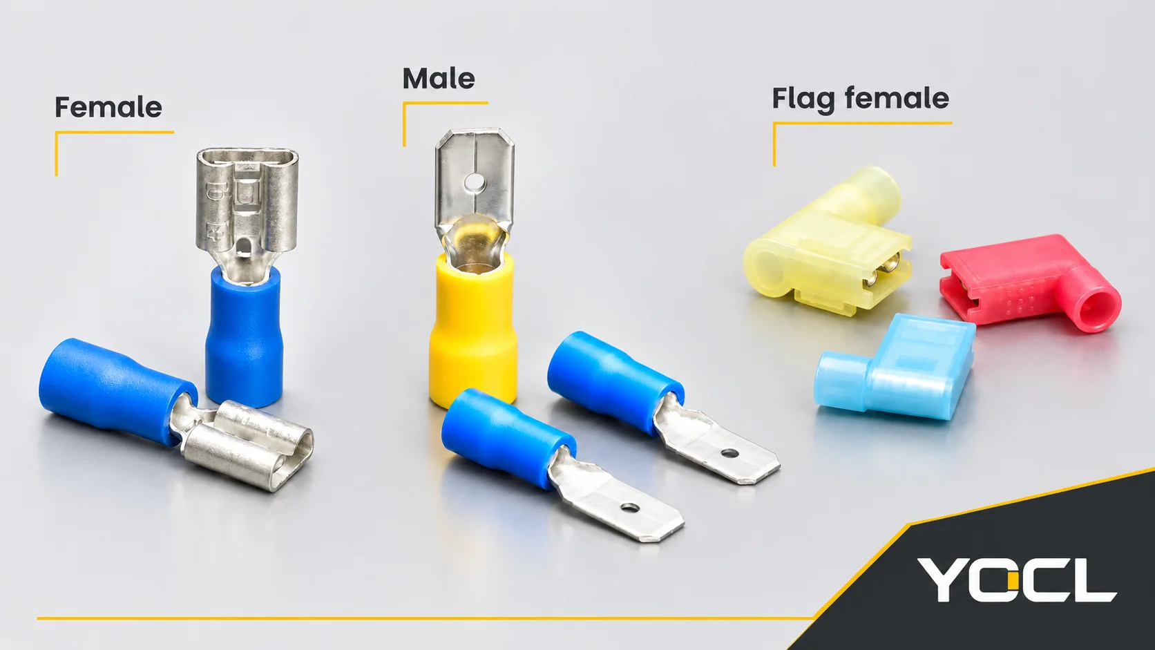
YOCL’s quick disconnect terminal size chart matches wire range to mating-tab width and thickness. The listed tab widths are 2.8, 4.75, 5.2, 6.35, 8.0 and 9.4 mm. Red terminals cover 0.5–1.5 mm², blue 1.5–2.5 mm², and yellow 4–6 mm². Select the conductor group first, match both tab dimensions, then choose single- or double-crimp construction.
Master quick-reference matrix
This quick disconnect terminal size chart covers straight female FDD/FDVD, straight male MDD/MDVD and nylon flag female FLDNY terminals. The group number identifies a wire range, not a single cross-section. American Wire Gauge (AWG) ranges are shown alongside square millimetres.
| Group | Colour | Conductor range (mm²) | AWG | FDD/FDVD female specifications: max current (A) | MDD/MDVD male specifications: Imax (A) | FLDNY specifications: Imax (A) |
|---|---|---|---|---|---|---|
| 1.25 | Red | 0.5–1.5 | 22–16 | 19 | 10 | 10 |
| 2 | Blue | 1.5–2.5 | 16–14 | 27 | 15 | 15 |
| 5.5 | Yellow | 4–6 | 12–10 | 48 | 24 | — |
— means current not specified. For FLDNY 5.5-250, send YOCL the intended load and mating-tab details for confirmation before specifying operating current.
Use the linked YOCL specifications for FDD/FDVD female terminals, MDD/MDVD male terminals and FLDNY flag female terminals with this matrix. Their current entries are conductor-group maxima; read the selection limits below before applying them to a connection.
Understanding female and male current figures
YOCL’s female-terminal specifications list 19 / 27 / 48 A, while the male-terminal specifications list 10 / 15 / 24 A for the corresponding conductor groups. Keep the two sets separate: a female-terminal figure cannot be assigned to its male counterpart.
For a proposed female/male combination, use the lower published figure as a preliminary selection ceiling, then confirm the exact models for the intended load. These group entries have no published test conditions and do not establish a tested pair current or installed-wire ampacity.
Conductor ampacity and contact capability are separate engineering checks. Wire ampacity concerns the conductor in its installation; contact capability concerns the actual terminal and mating connection. These group figures do not establish separate wire or contact test results. Check the equipment connection requirements as well as the terminal model.
Large wire barrels with narrow tabs need model-specific confirmation
A larger wire barrel does not establish the current capability of a smaller mating interface. The yellow group includes FDD5.5-110 × 5 and MDD 5.5-110(5), which accept 4–6 mm² conductors but specify a 0.5 × 2.8 mm tab. It also includes 187 variants with 4.75 mm tab width.
Do not automatically assign the male specifications’ 24 A group maximum to every yellow narrow-tab model. Specify the complete part number, tab width and thickness, mating component and intended current for model-specific confirmation. Neither barrel colour nor tab width alone supplies a numerical current limit or a derating factor.
Tab codes: select by width and thickness together
The suffixes are legacy inch codes expressed in thousandths of an inch. Use the code to find the catalogue row, then select by the specified millimetre dimensions. Do not replace the stated width with a rounded interpretation of the suffix.
| Tab suffix | Published width (mm) | FDD/FDVD female | MDD/MDVD male | FLDNY flag female |
|---|---|---|---|---|
| 110 | 2.8 | Listed | Listed | — |
| 187 | 4.75 | Listed | Listed | Listed |
| 205 | 5.2 | Listed | — | — |
| 250 | 6.35 | Listed | Listed | Listed |
| 312 | 8.0 | Listed | — | — |
| 375 | 9.4 | Listed | — | — |
Availability varies by conductor group; use the detailed rows for the actual combinations. Here, a dash means no corresponding model is listed in that series.
The 205, 312 and 375 female rows have no MDD/MDVD counterpart in these specifications. For an equipment-tab connection, the equipment maker’s tab drawing governs the interface; the female model alone does not establish the equipment dimensions.
For an existing tab, isolate the equipment, verify it is de-energized and disconnect the terminal before measuring. Measure both the flat blade’s width and its metal thickness with a suitable measuring instrument. Record them separately and compare them with the same catalogue row. Width alone cannot distinguish the listed thickness alternatives, and an insulation-body measurement is not the tab measurement.
All tab columns below use thickness × width. Keep that order on the BOM to prevent a width-first measurement from being transcribed into the wrong field.
Decode the series, group and suffix
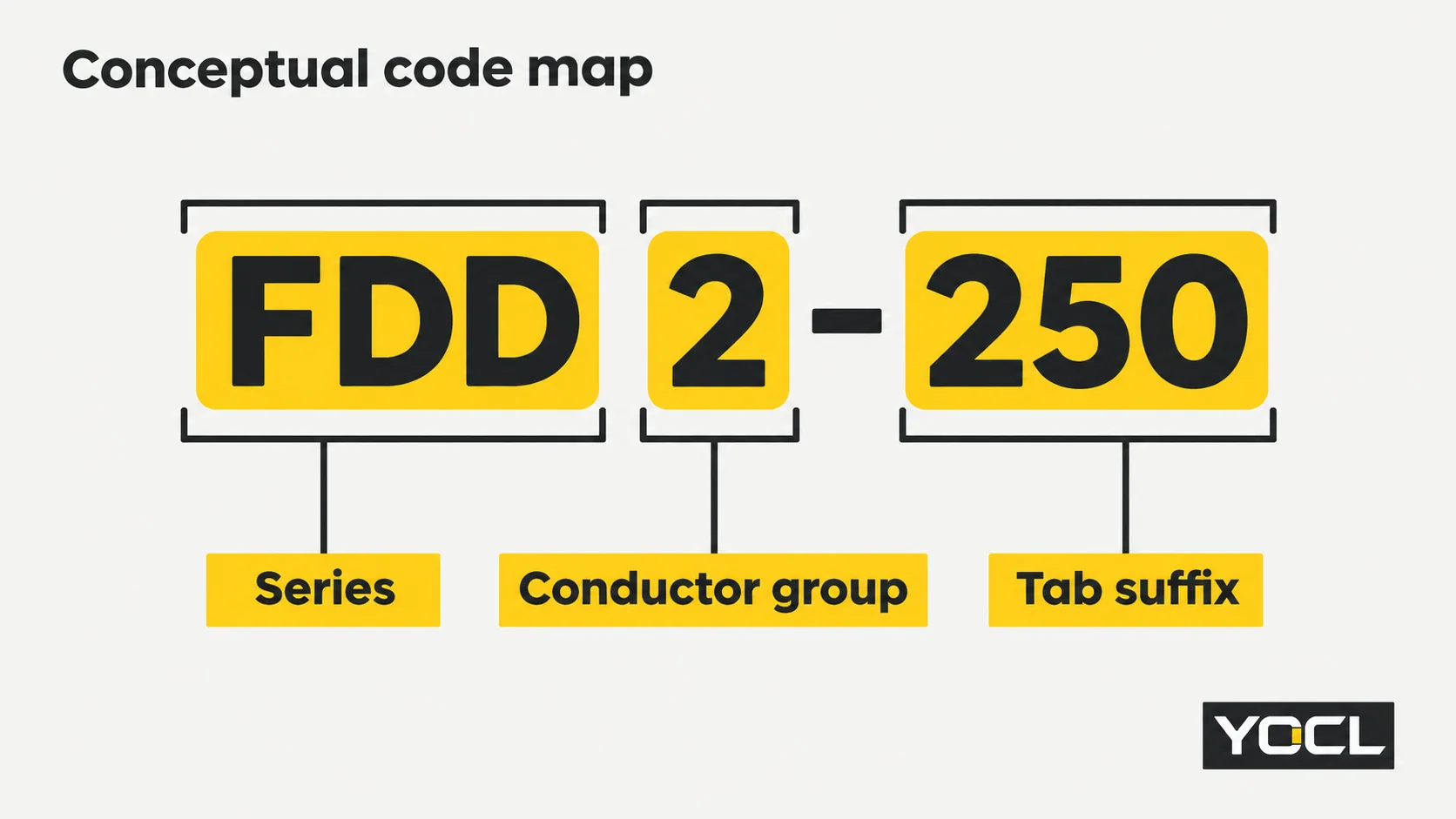
Read FDD2-250 as series FDD, conductor group 2 and tab suffix 250. The series identifies the construction; the group points to the conductor chart; the suffix points to the tab row. These fields answer different questions and cannot substitute for one another.
FDD and MDD are the single-crimp female and male versions. FDVD and MDVD are double-crimp versions with an additional copper tube and sleeve. These straight terminals use brass contacts and polyvinyl chloride (PVC) insulation. FLDNY is the right-angle female form with a nylon sleeve.
For a fully covered female connection, compare FDFD/FDFVD PVC-insulated terminals and FDFNY nylon-insulated terminals. A PBDNY/PBDNYD piggyback terminal combines male and female contact forms. Select these alternatives from their own drawings and specifications.
Where present, (5) and (8) identify tab thicknesses of 0.5 and 0.8 mm. The female 5.5 group instead prints × 5 and × 8 for those alternatives. Preserve that spelling when ordering. The 375 rows have a 1.2 mm tab thickness without either parenthetical mark.
Preserve the printed SKU when searching or sending an enquiry: female codes have no space after FDD/FDVD; male codes include a space after MDD/MDVD. If a search fails, check spaces, parentheses and the multiplication sign before assuming the part is unavailable. MDD 5.5-187 and MDVD 5.5-187 have no thickness suffix; their specified tab is 0.5 × 4.75 mm.
Dimension key: B, L1 and L2
B is the female receptacle’s outside width, or the male tab’s blade width. L1 is the single-crimp terminal’s overall length; L2 is the double-crimp terminal’s overall length. The female receptacle’s external B dimension is therefore different from the width of the tab it accepts.
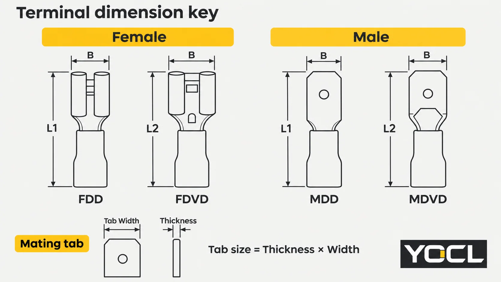
Use B and the appropriate overall length for space checks, and the tab column for mating size. Other drawing dimensions are available with the linked product specifications for checking the complete installation envelope.
FDD/FDVD female dimension chart
All 22 paired rows are grouped by colour and wire range for direct lookup. Dimensions are in millimetres. Choose FDD or FDVD for the required crimp construction; the matching overall length is L1 or L2 respectively.
Red — group 1.25: 0.5–1.5 mm² / AWG 22–16
| FDD single-crimp model | FDVD double-crimp model | Tab: thickness × width | B | L1 | L2 |
|---|---|---|---|---|---|
| FDD1.25-110(5) | FDVD1.25-110(5) | 0.5 × 2.8 | 3.3 | 18.5 | 20.0 |
| FDD1.25-110(8) | FDVD1.25-110(8) | 0.8 × 2.8 | 3.3 | 18.5 | 20.0 |
| FDD1.25-187(5) | FDVD1.25-187(5) | 0.5 × 4.75 | 5.0 | 19.0 | 20.5 |
| FDD1.25-187(8) | FDVD1.25-187(8) | 0.8 × 4.75 | 5.0 | 19.0 | 20.5 |
| FDD1.25-205 | FDVD1.25-205 | 0.5 × 5.2 | 5.7 | 19.0 | 20.5 |
| FDD1.25-250 | FDVD1.25-250 | 0.8 × 6.35 | 6.6 | 19.8 | 21.3 |
| FDD1.25-312 | FDVD1.25-312 | 0.8 × 8.0 | 8.2 | 23.0 | 24.5 |
Blue — group 2: 1.5–2.5 mm² / AWG 16–14
| FDD single-crimp model | FDVD double-crimp model | Tab: thickness × width | B | L1 | L2 |
|---|---|---|---|---|---|
| FDD2-110(5) | FDVD2-110(5) | 0.5 × 2.8 | 3.3 | 18.5 | 20.0 |
| FDD2-110(8) | FDVD2-110(8) | 0.8 × 2.8 | 3.3 | 18.5 | 20.0 |
| FDD2-187(5) | FDVD2-187(5) | 0.5 × 4.75 | 5.0 | 19.0 | 20.5 |
| FDD2-187(8) | FDVD2-187(8) | 0.8 × 4.75 | 5.0 | 19.0 | 20.5 |
| FDD2-205 | FDVD2-205 | 0.5 × 5.2 | 5.7 | 19.0 | 20.5 |
| FDD2-250 | FDVD2-250 | 0.8 × 6.35 | 6.6 | 19.0 | 20.5 |
| FDD2-312 | FDVD2-312 | 0.8 × 8.0 | 8.2 | 23.7 | 25.2 |
| FDD2-375 | FDVD2-375 | 1.2 × 9.4 | 9.9 | 27.6 | 29.1 |
Yellow — group 5.5: 4–6 mm² / AWG 12–10
| FDD single-crimp model | FDVD double-crimp model | Tab: thickness × width | B | L1 | L2 |
|---|---|---|---|---|---|
| FDD5.5-110 × 5 | FDVD5.5-110 × 5 | 0.5 × 2.8 | 3.3 | 21.0 | 22.5 |
| FDD5.5-110 × 8 | FDVD5.5-110 × 8 | 0.8 × 2.8 | 3.3 | 21.0 | 22.5 |
| FDD5.5-187 × 5 | FDVD5.5-187 × 5 | 0.5 × 4.75 | 5.0 | 22.0 | 23.5 |
| FDD5.5-187 × 8 | FDVD5.5-187 × 8 | 0.8 × 4.75 | 5.0 | 22.0 | 23.5 |
| FDD5.5-250 | FDVD5.5-250 | 0.8 × 6.35 | 6.6 | 23.4 | 24.9 |
| FDD5.5-312 | FDVD5.5-312 | 0.8 × 8.0 | 8.2 | 27.3 | 28.8 |
| FDD5.5-375 | FDVD5.5-375 | 1.2 × 9.4 | 9.9 | 29.6 | 31.1 |
MDD/MDVD male dimension chart
The 14 paired rows use the same conductor-group ranges. Dimensions are in millimetres; L1 is MDD overall length and L2 is MDVD overall length. Match both tab dimensions to the required female receptacle or equipment interface.
Red — group 1.25: 0.5–1.5 mm² / AWG 22–16
| MDD single-crimp model | MDVD double-crimp model | Tab: thickness × width | B | L1 (MDD) | L2 (MDVD) |
|---|---|---|---|---|---|
| MDD 1.25-110(5) | MDVD 1.25-110(5) | 0.5 × 2.8 | 2.8 | 17.7 | 18.2 |
| MDD 1.25-110(8) | MDVD 1.25-110(8) | 0.8 × 2.8 | 2.8 | 17.7 | 18.2 |
| MDD 1.25-187(5) | MDVD 1.25-187(5) | 0.5 × 4.75 | 4.75 | 20.0 | 20.5 |
| MDD 1.25-187(8) | MDVD 1.25-187(8) | 0.8 × 4.75 | 4.75 | 20.0 | 20.5 |
| MDD 1.25-250 | MDVD 1.25-250 | 0.8 × 6.35 | 6.35 | 21.0 | 21.5 |
Blue — group 2: 1.5–2.5 mm² / AWG 16–14
| MDD single-crimp model | MDVD double-crimp model | Tab: thickness × width | B | L1 (MDD) | L2 (MDVD) |
|---|---|---|---|---|---|
| MDD 2-110(5) | MDVD 2-110(5) | 0.5 × 2.8 | 2.8 | 17.7 | 18.2 |
| MDD 2-110(8) | MDVD 2-110(8) | 0.8 × 2.8 | 2.8 | 17.7 | 18.2 |
| MDD 2-187(5) | MDVD 2-187(5) | 0.5 × 4.75 | 4.75 | 20.0 | 20.5 |
| MDD 2-187(8) | MDVD 2-187(8) | 0.8 × 4.75 | 4.75 | 20.0 | 20.5 |
| MDD 2-250 | MDVD 2-250 | 0.8 × 6.35 | 6.35 | 21.0 | 21.5 |
Yellow — group 5.5: 4–6 mm² / AWG 12–10
| MDD single-crimp model | MDVD double-crimp model | Tab: thickness × width | B | L1 (MDD) | L2 (MDVD) |
|---|---|---|---|---|---|
| MDD 5.5-110(5) | MDVD 5.5-110(5) | 0.5 × 2.8 | 2.8 | 20.0 | 20.5 |
| MDD 5.5-110(8) | MDVD 5.5-110(8) | 0.8 × 2.8 | 2.8 | 20.0 | 20.5 |
| MDD 5.5-187 | MDVD 5.5-187 | 0.5 × 4.75 | 4.75 | 22.0 | 22.5 |
| MDD 5.5-250 | MDVD 5.5-250 | 0.8 × 6.35 | 6.35 | 23.0 | 23.5 |
FLDNY flag female model summary
FLDNY terminals combine brass female contacts with nylon sleeves and a right-angle wire-entry arrangement. The seven models below use three listed plug-size combinations. Plug size is thickness × width in millimetres; Imax retains the FLDNY specifications’ conductor-group values.
| Model | Colour | Plug: thickness × width | FLDNY specifications: group Imax (A) |
|---|---|---|---|
| FLDNY 1.25-187(5) | Red | 0.5 × 4.75 | 10 |
| FLDNY 1.25-187(8) | Red | 0.8 × 4.75 | 10 |
| FLDNY 1.25-250 | Red | 0.8 × 6.35 | 10 |
| FLDNY 2-187(5) | Blue | 0.5 × 4.75 | 15 |
| FLDNY 2-187(8) | Blue | 0.8 × 4.75 | 15 |
| FLDNY 2-250 | Blue | 0.8 × 6.35 | 15 |
| FLDNY 5.5-250 | Yellow | 0.8 × 6.35 | — |
— means current not specified: request application confirmation for FLDNY 5.5-250. The FLDNY catalogue states 400 V and 105°C for this series only. These catalogue declarations do not extend to FDD/FDVD or MDD/MDVD.
The flag form changes the wire-entry orientation relative to the receptacle. Use its own model drawing when the available space dictates that form; selecting a flag model by the straight-terminal length would compare different drawing fields.
Worked reading: blue group onto an equipment tab
Assume a 2.5 mm² conductor and an equipment tab measured as 6.35 mm wide × 0.8 mm thick. The conductor falls within the blue group’s 1.5–2.5 mm² range. Written in the source-table order, the interface is 0.8 × 6.35 mm, which identifies the 250 row.
The female options are FDD2-250 for single crimp or FDVD2-250 for double crimp. If the project also requires a separate male terminal, the dimensionally corresponding blue models are MDD 2-250 and MDVD 2-250. An equipment tab already present is not automatically one of those male products: its own documentation still governs.
For the proposed YOCL female/male combination, the male specifications’ 15 A is the lower preliminary selection ceiling; the female specifications’ 27 A does not raise it. Confirm the complete connection for the load before use. Record both part numbers, conductor size, tab dimensions and crimp construction on the BOM so purchasing can reproduce the selection.
For the broader connection-style terminology, use what a crimp terminal is. If the actual connection is a screw or stud tongue, ring versus spade terminals addresses that separate choice.
Questions about the size codes
Is a 187 terminal 4.8 mm or 4.75 mm?
YOCL’s relevant rows specify 4.75 mm. The 187 suffix is the legacy inch code; select by the stated millimetre width and the row’s thickness. Do not substitute a rounded width when specifying the interface.
Can I use the female specifications’ 48 A for a 5.5 pair?
No. The female specifications list 48 A, while the male specifications list 24 A for that group. Use the lower entry for preliminary selection and confirm the exact models, particularly when a large wire barrel is paired with a narrow tab.
Does the group number equal the wire size?
No. The group number points to the published wire range. Read that range directly; colour and group number do not specify a single conductor area or identify the mating-tab dimensions.
My tab is 5.2 mm wide—is there a male MDD to match?
The MDD/MDVD specifications contain no 205 row. That width appears in FDD/FDVD female rows; use the equipment-tab drawing to establish its thickness and other interface requirements before choosing a receptacle.
What do red, blue and yellow quick disconnect colours mean?
For these YOCL series, red identifies 0.5–1.5 mm² / AWG 22–16, blue 1.5–2.5 mm² / AWG 16–14, and yellow 4–6 mm² / AWG 12–10. Colour identifies the wire group; select tab size and construction separately.
What is the difference between FDD and FDVD?
FDD uses single-crimp construction; FDVD adds a copper tube sleeve for double crimp. Specify that construction in the part number and match it to the required crimping tooling. For packaging clearance, use the FDVD row’s L2 rather than the FDD row’s L1.
Browse YOCL quick disconnect series & request a quote
- FDD/FDVD female terminals — straight female receptacles, single- or double-crimp construction.
- MDD/MDVD male terminals — straight male tab terminals and paired model dimensions.
- FLDNY nylon flag female terminals — right-angle female terminals with nylon insulation.
Send YOCL your BOM for quotation and selection review. Include full part numbers, quantities, wire ranges, mating-tab dimensions and intended load, together with the equipment drawing where available. Identify any large-barrel/narrow-tab combination and request the missing FLDNY yellow-group current information when applicable.