
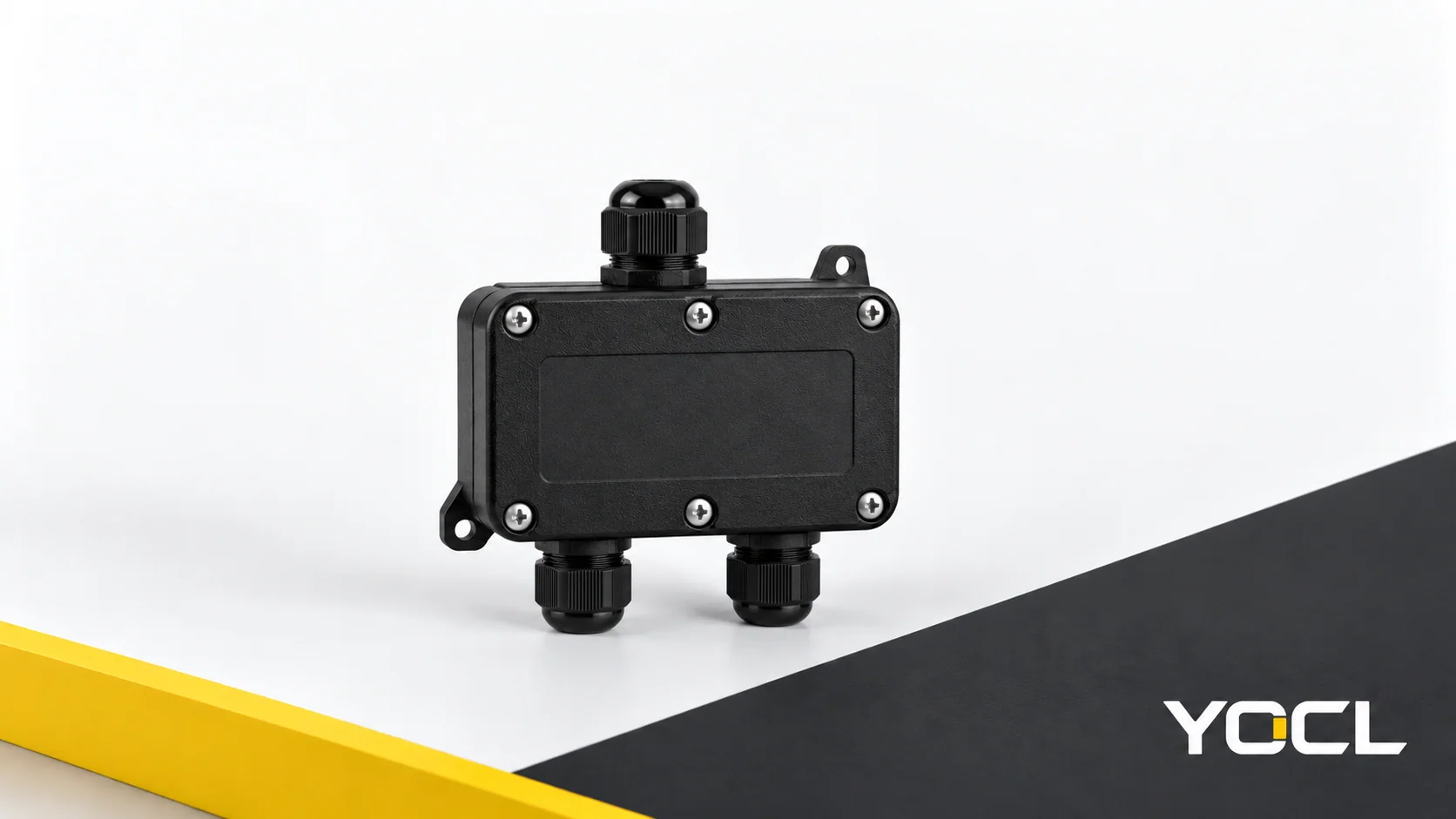
Waterproof junction boxes enclose cable joints in a body with a sealed cover and sealed cable entries. In a preconfigured box, internal terminals join individual conductors. The entry seal fits the cable’s outer jacket; the terminal fits the prepared conductor. An ingress protection (IP) rating describes enclosure protection under specified conditions; electrical compatibility requires separate terminal information.
For compact multi-entry boxes, keep three questions separate: what closes the enclosure, what seals each cable, and what joins the conductors. Each question leads to a different dimension, interface or document.
Three parts, three different questions
Use the following map to locate the information you need before comparing models.
| Part of the junction box | Question it answers | Where the deeper answer belongs |
|---|---|---|
| Body, cover and perimeter seal | How is the enclosure closed? | Exact-model assembly drawing and cover/seal instructions |
| Cable entries and their seals | How does each cable pass through the enclosure boundary? | Cable-diameter range, fitting-to-body details and, for separate fittings, cable gland selection |
| Internal terminals or connection device | How are individual conductors joined? | The supplied terminal’s connection diagram, conductor specification and electrical ratings |
The complete arrangement matters. The International Electrotechnical Commission (IEC) classifies enclosure protection and points to manufacturer information and relevant product standards for its application. Keep the box’s ingress declaration attached to its documented configuration. Separate component labels do not establish that configuration. IEC 60529 scope preview.
The cover seam is one sealing boundary
The cover seam is where the lid meets the body. In a gasketed construction, the perimeter seal follows that boundary. Cable-entry seals act at separate openings, so a closed lid answers only part of the sealing question.
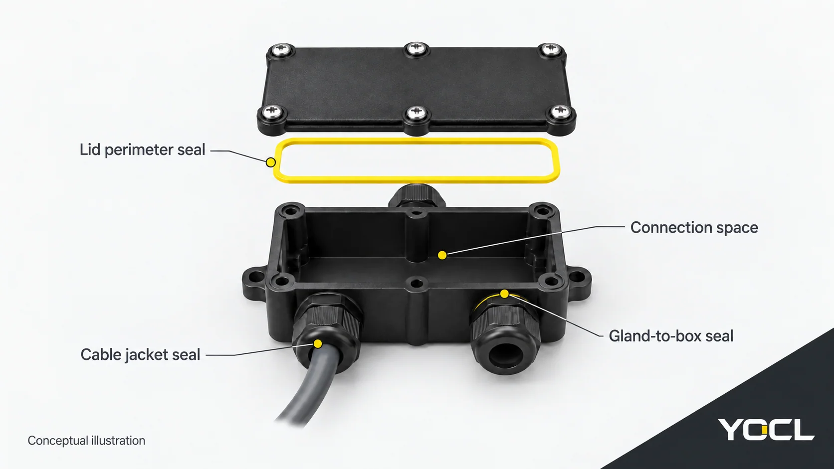
The assembly drawing should identify the seal position, the cover fastening arrangement and the components required to close the box. Any tightening value belongs to that model’s instructions. A generic photograph cannot establish the required assembly condition.
Unused cable openings also belong in the enclosure boundary. If fewer cables are used than the box has entries, ask which closure arrangement is specified for the remaining openings and included in the ingress declaration. Do not assume that an empty cable gland, a shipping cap and a documented blanking device are interchangeable.
Cable entries have two interfaces to understand
At a cable entry, distinguish the cable-to-seal interface from the entry-fitting-to-body interface. One surrounds the cable jacket; the other is where the entry fitting meets the enclosure. Integrated entries and separately mounted glands can have different construction, so use the actual drawing to identify both boundaries.
IEC 62444 defines cable glands by their entry, sealing and retention functions. Strain relief is an additional possible function; a verified strain-relief capacity must come from the particular gland’s declared performance. IEC 62444 public preview, Section 3.1.
Two measurements must stay separate:
- Cable outer diameter, in mm: the outside dimension of the jacket passing through the entry seal.
- Individual conductor cross-section, in mm²: the metal area of one conductor that the terminal must accommodate.
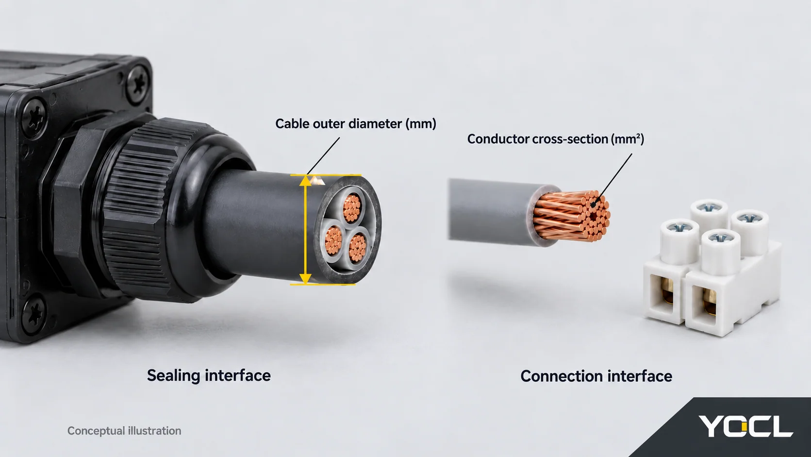
A conductor-area label does not state the cable’s outside diameter. For a separate gland, the mounting thread is another specification: it describes the fitting’s attachment to the enclosure. The thread designation and the cable sealing range answer different questions. Detailed dimensional and functional selection belongs in the linked gland guide.
Connections inside the box need their own information
The connection device joins the conductors inside the protected space. The box body provides enclosure; it does not identify which conductors share an electrical connection.
Cable-entry count is not terminal pole count. Three entries describe three cable access positions. They do not reveal the number of conductors in each cable, the number of separate terminal poles or the connection scheme. Obtain the actual terminal diagram before interpreting a box as a branching connection.
For the supplied terminal, the relevant information includes conductor size and type, permitted preparation, connection arrangement and electrical ratings. A current rating must remain attached to the confirmed terminal configuration. Likewise, a permitted conductor-size range does not establish a safe operating current for every cable or application within that range.
Read one compact box specification
The current YOCL F3-3T product information provides a useful example of how these fields differ.
| Field | F3-3T catalogue declaration | How to read it |
|---|---|---|
| Cable entries | 3 | Physical cable access positions; terminal poles require separate information |
| Cable outer diameter options | 5–8 mm or 9–12 mm | Separate listed seal options, each relating to the cable jacket |
| Conductor cross-section | 0.5–10 mm² | Individual conductor area for the stated terminal configuration |
| Connection method | Screw compression | The terminal connection method; preparation and tightening details require matching instructions |
If your measured cable diameter is 8.5 mm, it falls outside both listed seal ranges. The terminal’s 0.5–10 mm² conductor range does not change that result. Confirm a suitable seal option rather than treating the two options as one continuous 5–12 mm range.
These are first-party catalogue declarations. Use documentation matching the actual supplied terminal option to establish its electrical ratings and connection details.
Read the ingress claim in context
In IEC 60529, IP68 combines dust-tight protection with a continuous-immersion category. Ask for the applicable depth, duration and configured assembly rather than inferring them from the two digits. IEC 60529 public standard excerpts.
Immersion and water jets are separate exposures. IEC 60529 specifies that water numerals 7 or 8 alone do not require compliance with jet numerals 5 or 6 unless multiple coded. An IP68 label alone therefore does not establish jet-test performance. IEC 60529 Amendment 2, Clause 6.
The IP code also leaves influences such as condensation, corrosion and solar radiation to product standards. For moisture associated with temperature changes, read why condensation forms inside sealed electrical enclosures; that article explains the separate moisture mechanism. IEC 60529 scope preview.
For compact configurations, the YOCL waterproof connection box range brings the model options together. Compare the entry arrangement, cable seal option and confirmed terminal configuration as separate fields, then obtain the matching assembly and connection documents.
Related reading: waterproof connector interfaces and seals.
References
- IEC, Degrees of protection provided by enclosures (IP Code), IEC 60529, consolidated Edition 2.2, 2013: public scope preview and public standard excerpts. Limited sections consulted; not full paid-standard access.
- IEC, Cable glands for electrical installations, IEC 62444:2010 — public preview, Section 3.1.
- YOCL ELECTRIC, F3-3T Mini Waterproof Junction Box — product information. Catalogue declarations checked 7 October 2026.
- IEC, IEC 60529:1989/AMD2:2013 — public amendment preview, Clause 6.