
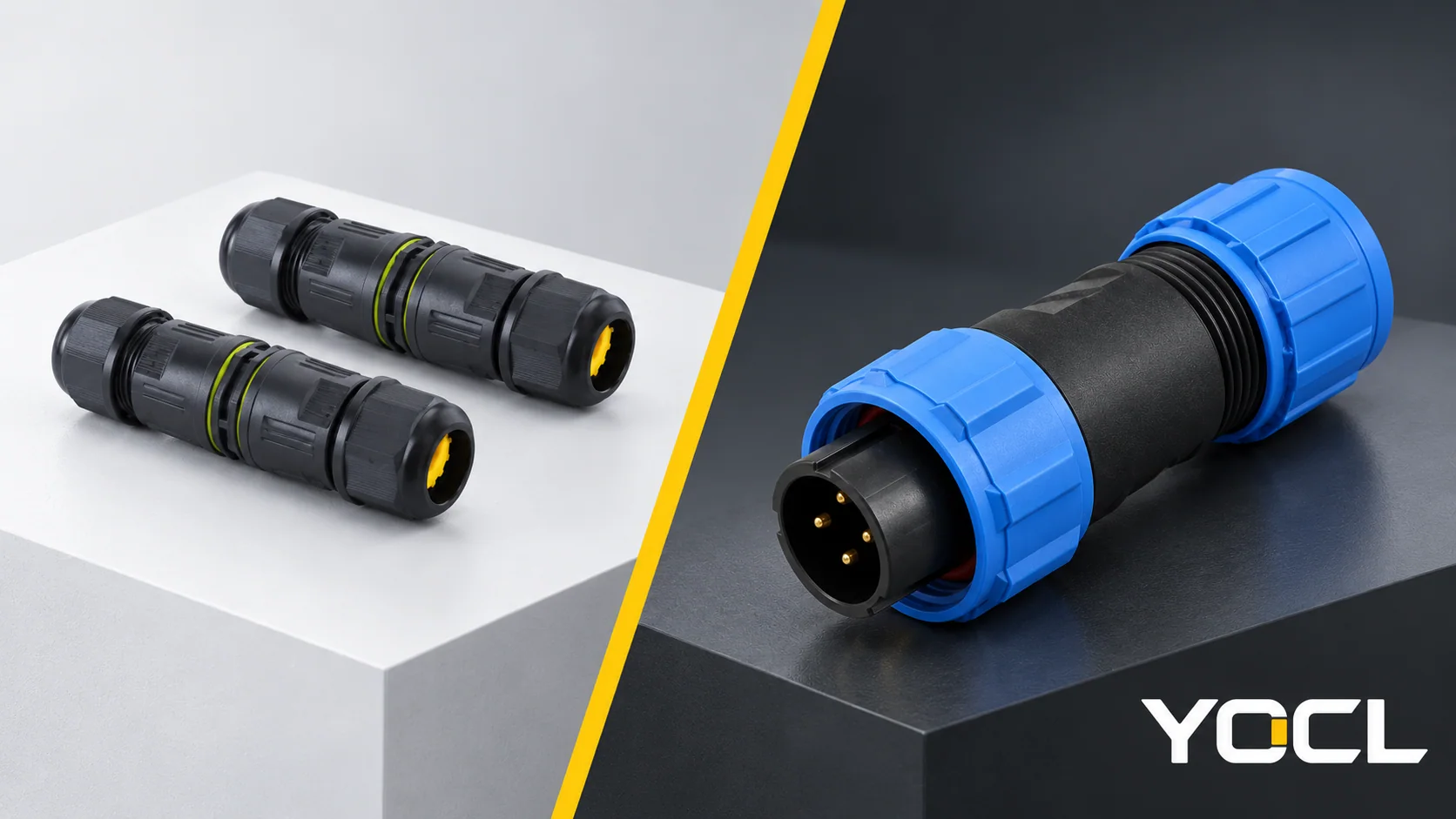
A waterproof connector combines an electrical connection with a construction intended to restrict water ingress under specified assembly and exposure conditions. The term covers several different products: an enclosed inline cable joint, a branching joint, or a detachable circular connector with a mating interface.
The first question is therefore what connection must the product make? A fixed cable joint and a plug-and-socket interface have different service arrangements and sealing boundaries. The cable, contacts, housing, seals and connected state must all match the selected configuration. A waterproof label alone does not describe those details.
Start With the Connection Structure
Use the physical connection task to find the appropriate product family before comparing ratings or cable ranges.
| Connection task | Product path | What the next document must establish |
|---|---|---|
| Join cables along one route | Inline cable joint | Conductor connections, entry seals at both ends and exact cable acceptance. |
| Connect a branch to a cable route | T-, Y- or cross-form joint | Entry layout and the actual electrical connection map; housing shape alone does not establish circuit topology. |
| Disconnect and reconnect through a defined mating pair | Circular cable connector | Both mating part numbers, contact arrangement, coupling method and protection in the required state. |
| Connect a cable to an equipment boundary | Cable plug with compatible panel connector | Mating pair, panel mounting and sealing, cable entry and service space. |
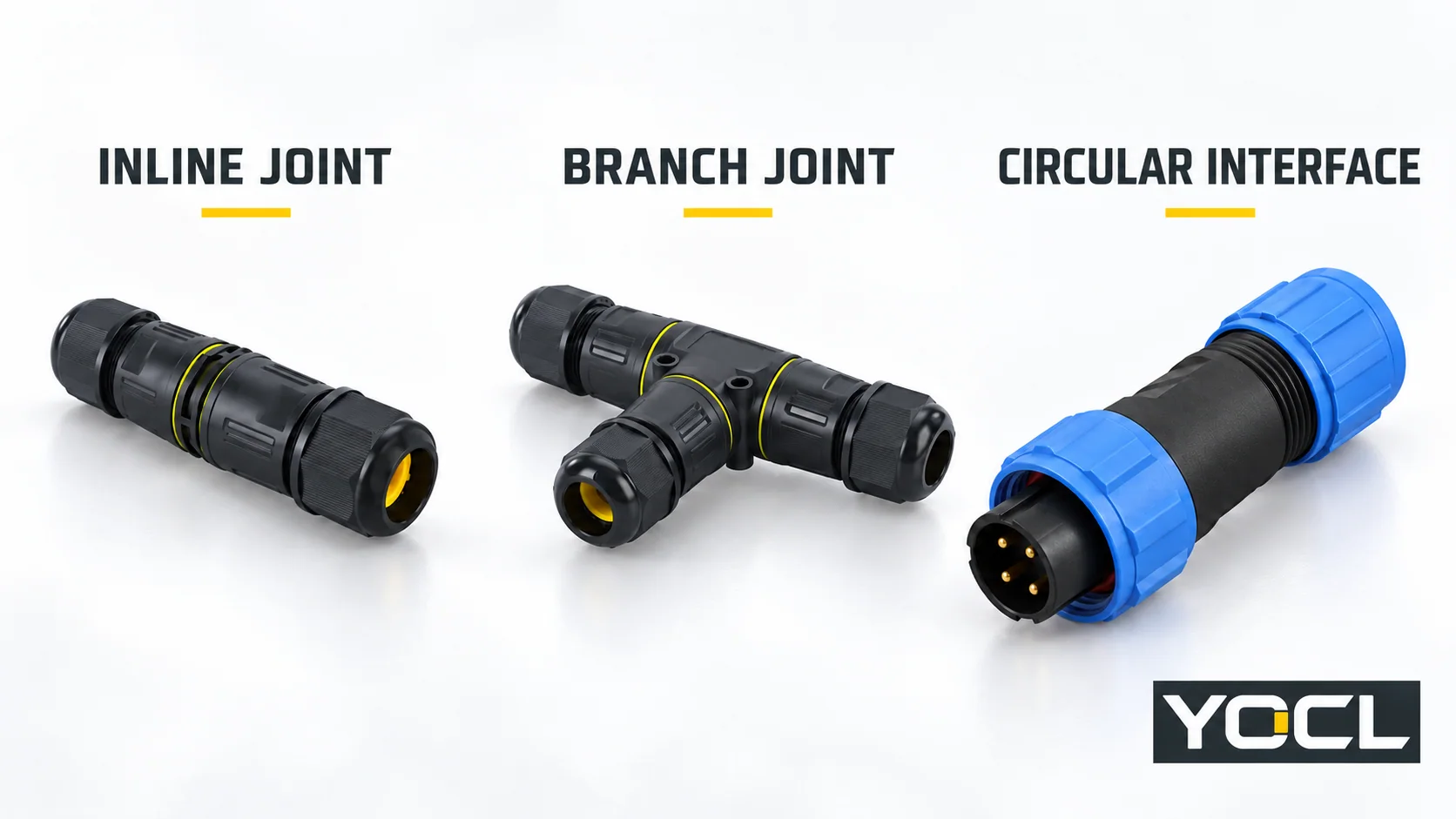
The YOCL waterproof connector range brings these paths together. An electrical sketch and a cable-route sketch help distinguish the required connection from a similar-looking product.
Inline and Branch Joints: Follow the Conductors and Every Entry
An enclosed inline joint connects conductors within a housing that accepts cables at its entries. A branch-form housing provides additional entry directions. The terminal construction inside can vary even when the outer bodies look similar.
For example, YOCL’s VO-ZXM20 Mini Waterproof Connector is described as an inline joint with screw terminals. Its product page separates order codes by core count and cable outside-diameter range. Those fields answer different questions: the core count concerns the electrical configuration, while cable outside diameter concerns the cable-entry fit. Neither should be inferred from the other.
The same principle applies to a branching product. Three cable entries do not tell you which conductors are common, which remain separate, or whether every branch carries the same permitted load. Obtain the wiring arrangement for the exact version. Do not use a T-shaped photograph as an electrical schematic.
A housing that can be opened for assembly is also different from a connector designed to separate through a defined mating interface. Unscrewing a cable-entry nut or opening the joint to access its terminals is not the same service operation as uncoupling a specified plug and socket.
For conductor-clamping methods and circuit arrangements, use the wire connector overview. This Hub keeps those details at orientation level so that the required connection family remains clear.
Circular Interfaces: Specify Both Sides of the Pair
A detachable circular connector adds an intentional mating boundary. Contacts on one half engage the designated contacts on the other, while the coupling mechanism secures the pair. Cable-mounted and panel-mounted formats introduce different mechanical and sealing requirements.
YOCL provides two circular product routes:
- LP quick-lock connectors: the current LP range describes pushbutton snap locking and screw-clamp termination, with cable and panel formats.
- SP threaded connectors: the current SP range describes threaded coupling, with contact arrangements, termination choices and cable or panel formats that depend on the selected series and configuration.
Here, quick-lock describes the mating mechanism. By comparison, quick-insert on a wire-joint product can describe how a conductor is terminated. Those names do not make the products interchangeable or establish the same conductor acceptance.
Specify both halves of a circular pair. The family name or nominal size is not enough: contact count, contact orientation, keying, termination, mounting format and cable-entry options must agree with the exact mating information. Similar shell diameters do not prove that different series or brands can mate safely.
The ability to carry current is another question from permission to mate or disconnect in a particular electrical condition. Do not treat a detachable form, latch or threaded collar as authorization to disconnect under load. Use the equipment and connector instructions for operation and servicing. The IEC 61984 public catalogue identifies a connector safety standard with a defined application scope; its existence does not establish compliance or a permitted switching duty for a particular YOCL configuration.
Separate the Electrical Path From the Water Boundaries
A useful mental model has two parallel checks: does the product make the intended electrical connection, and what boundaries must keep water out? A correct contact arrangement does not verify the seals. A sealed-looking housing does not verify the circuit.
| Boundary or function | Information to find |
|---|---|
| Conductor to terminal or contact | Conductor material, construction and cross-section; preparation and termination instructions; permitted conductor combination. |
| Cable jacket to entry seal | Actual cable outside diameter and shape, seal option, jacket compatibility and installation requirements. Check each entry. |
| Housing joints | Required housing parts, seals, assembly state and instructions for the exact product. |
| Circular mating interface | Designated pair, coupling condition, seal arrangement and protection claimed for connected or other specified states. |
| Panel interface, when present | Panel opening, wall thickness, mounting parts, seal and installation requirements for the selected panel connector. |
| Electrical duty | Contact-specific current and voltage information and the conditions applicable to the complete configuration. |
This map identifies questions rather than prescribing a universal seal construction. An exterior product photograph cannot establish hidden seal placement, contact paths or a complete installed assembly’s performance.
Read “Waterproof” With the Specified State and Exposure
The IEC 60529 public scope describes classification of degrees of protection provided by enclosures using the IP Code. It is a framework for protection claims, not evidence that every connector sold as waterproof has been tested in every possible condition.
For the product being considered, obtain the declared protection, supporting evidence, applicable cable and seal configuration, assembly instructions and exposure conditions. Ask whether the stated protection applies when connected, disconnected, capped or panel-mounted. A rating for one state does not automatically describe another.
YOCL’s LP range, for example, states that its listed IP68 protection applies in the connected state. That is a product-range declaration. It is not evidence of protection for an uncovered disconnected contact face, approval of an arbitrary cable, or suitability for indefinite underwater service. Confirm the selected model’s actual exposure conditions and documentation.
Rain, washdown and immersion are different requirements to communicate to the supplier. So are dust, chemicals, sunlight and temperature. Avoid using a generic IP label as a substitute for the conditions the product will actually encounter. Where the documentation does not identify the required configuration or exposure, leave suitability unresolved until it is confirmed.
Distinguish a Connector, Cable Gland and Junction Box
These products can appear in the same installation but perform different jobs.
A connector joins electrical conductors or contacts. A cable gland provides a cable-entry interface and does not, by itself, join the electrical circuit; the cable gland overview explains its product branches. A junction box provides an enclosure around connections and introduces its own cover and entry boundaries, as described in the waterproof junction box overview.
A panel connector may itself meet an enclosure wall, and an inline joint may include cable-entry seals. These overlaps do not make a gland, box and connector interchangeable. Choose the architecture first, then verify its component and assembly requirements.
Follow the Question to the Right Resource
| Your next question | Useful next resource or document |
|---|---|
| Which conductor-clamping or common/isolated circuit arrangement is needed? | Wire connector overview and the exact terminal’s wiring information. |
| Is the task a fixed inline or branching joint? | Waterproof connector range and the chosen VO version’s conductor, entry and circuit details. |
| Is a quick-lock detachable cable or panel interface needed? | LP connector range and the mating-pair documents. |
| Is a threaded circular interface needed? | SP connector range and the exact contact, termination and mounting configuration. |
| How should entries be arranged in a separate enclosure? | Cable-entry planning for a waterproof junction box. |
For a model enquiry, provide the required connection structure, a circuit sketch, contact or core count, conductor details, cable jacket diameters, electrical duty, mounting format and exposure. For a detachable assembly, include both sides of the pair and the required connected or disconnected condition. These inputs let YOCL identify relevant product documents without treating a housing photograph as a finished specification.
References
- YOCL ELECTRIC, VO-ZXM20 Mini Waterproof Connector, product information on inline screw-terminal construction and configuration choices.
- YOCL ELECTRIC, LP Quick-Lock Waterproof Connectors, range information on coupling, termination, mounting formats and connected-state protection.
- YOCL ELECTRIC, SP Waterproof Circular Connectors, range information on threaded coupling and configuration choices.
- International Electrotechnical Commission, IEC 61984:2008 — Connectors: Safety Requirements and Tests, public catalogue scope only.
- International Electrotechnical Commission, IEC 60529 consolidated edition 2.2 — Degrees of Protection Provided by Enclosures (IP Code), public catalogue scope only.