
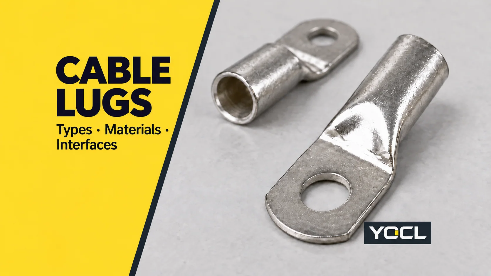
A cable lug is a conductive termination fitted to a cable conductor so it can connect to an equipment terminal, stud or busbar. A typical compression lug combines a conductor-receiving barrel with a bolted palm; a pin lug uses an insertion end. Both interfaces must suit the connection.
The useful starting question is: how does the cable enter the lug, and how does the lug connect to the equipment? “Copper,” “compression” and “two-hole” can all describe the same part. They answer different questions.
Where the lug sits in the connection
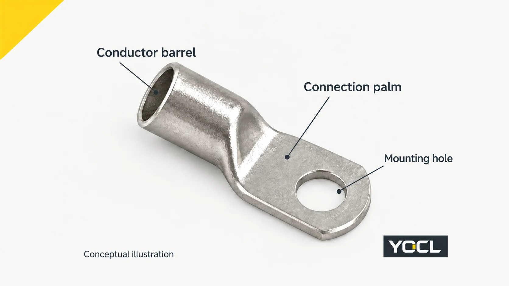
A conventional tubular lug has a barrel that receives the conductor and a palm that contacts the equipment terminal. The palm’s mounting hole accommodates the specified fastening arrangement. YOCL’s SC(JGA) copper cable lugs illustrate this barrel-to-flat-palm form.
The barrel connection secures the conductor and provides its conductive connection to the lug. The equipment end provides the next contact in the current path. A lug is a connection component; it does not provide circuit interruption or overcurrent protection.
Some lugs replace the bolted palm with a pin that enters a compatible equipment terminal. That changes the equipment interface without removing the need to match the conductor end.
Cable lug types describe three different things
Use three independent labels when identifying a lug:
| Classification | Common descriptions | What it tells you |
|---|---|---|
| Conductor connection | Compression/crimp; mechanical/bolted | How the cable is secured in the barrel |
| Body material | Copper; aluminium; copper–aluminium bimetallic | The declared material construction |
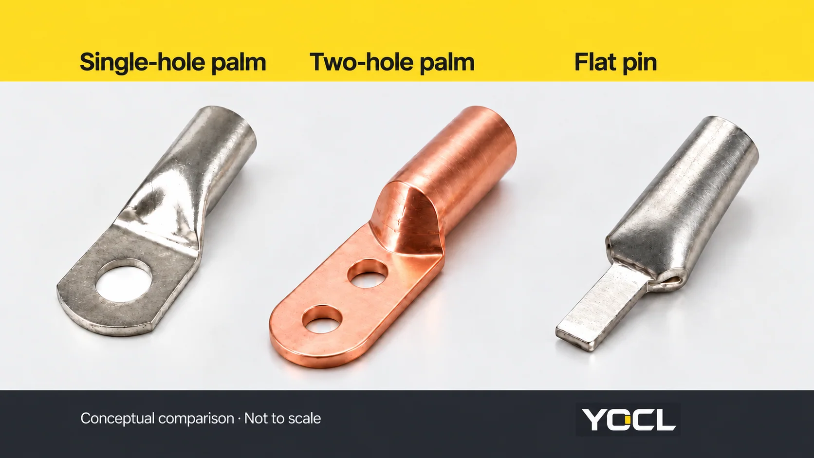
| Equipment interface | Single-hole palm; two-hole palm; pin | How the lug meets the receiving terminal |
For example, a compression copper lug with a two-hole palm belongs to all three categories. Calling it simply a “copper lug” leaves the joining method and mounting pattern unspecified.
Compression and mechanical lugs
With a compression lug, the specified crimping process deforms the barrel around the conductor. Selection includes the conductor and the matching lug, die and tool requirements; fitting the cable into an uncrimped barrel does not establish a completed connection.
A mechanical lug secures the conductor through a bolted mechanism. YOCL’s mechanical cable lug range includes BLMT shear-bolt designs. These secure the conductor without a crimping operation, but still require the model’s preparation, tooling and bolt instructions.
“Mechanical” does not mean every size or conductor construction is accepted. Equally, a compression lug’s stated conductor size does not identify a universal crimp die.
The equipment end determines the mating interface
Match the lug’s equipment end to the receiving connection before comparing similar-looking parts.
| Interface | Physical form | Receiving-side checks | YOCL example |
|---|---|---|---|
| Single-hole palm | Flat contact face with one mounting hole | Hole diameter, palm footprint, contact arrangement and space | SC(JGA) |
| Two-hole palm | Extended contact face with two mounting holes | Both hole diameters and their centre-to-centre spacing | DT-2 two-hole copper lugs |
| Flat pin | Narrow projecting insertion end | Pin width, thickness, usable length and terminal acceptance | C45 copper pin terminal |
A two-hole lug is not specified completely by its cable size and one hole diameter. The mounting pattern also has to match. DT-2 drawings identify hole diameter as Φ and hole-centre spacing as L3.
For a pin lug, an apparently suitable opening is only part of the check. The terminal must accept that pin geometry and termination arrangement. The C45 designation does not prove compatibility with every C45-type circuit breaker.
Materials and surface finishes have different meanings
Copper lugs are a starting family for copper-conductor connections. A copper body may have a coating such as tin: a tinned copper lug is still copper underneath. A silver appearance alone does not identify the base material or establish aluminium-conductor acceptance.
Aluminium lugs use an aluminium body. Their conductor compatibility must come from the exact product’s declared acceptance, rather than the material name alone.
Bimetallic lugs combine two metals in a defined arrangement. YOCL’s DTL-2 connecting terminal uses an aluminium conductor barrel and a copper connection palm. That arrangement provides a material transition between the two ends; it is not an automatic approval for every dissimilar-metal connection or for reversed use.
For the deeper conductor-to-equipment material decision, use Copper vs Aluminium vs Bimetallic Cable Lugs. It covers compatibility, coatings and environmental considerations beyond this orientation guide.
Cable size and mounting-hole size are separate specifications
Conductor cross-section is an area, normally expressed in mm². A mounting-hole diameter or barrel bore is a length, expressed in mm. Neither dimension substitutes for a documented conductor rating.
Consider the published BLMT-25/95-13 model:
| Catalogue field | Published value | Meaning |
|---|---|---|
| Conductor range | 25–95 mm² | Listed conductor cross-section range |
| Palm hole Φ | 13 mm | Mounting-hole diameter |
| Barrel bore d | 12.5 mm | Internal barrel dimension |
| Overall length L | 75 mm | Installation-space dimension |
The 13 mm hole is not a 13 mm² cable rating, and the 12.5 mm bore does not by itself approve every conductor that fits. Confirm conductor material and construction as well as the listed range. The public scope of UL 486A-486B distinguishes conductor sizes and constructions, including other strand configurations identified by marking.
A lug, ferrule and splice serve different connection jobs
A cable lug gives the conductor an equipment connection, such as a palm or pin. A wire ferrule prepares a stranded conductor end for a compatible terminal; it does not add a bolted mounting palm. A splice connector joins conductors to each other rather than terminating one at an equipment contact.
A pin lug and a cord-end ferrule can both enter a terminal, but their geometry and accepted use can differ. See What Is a Wire Ferrule? Types, Sizes and Terminal Compatibility before treating them as interchangeable.
What evidence completes the specification?
A product-family name is an orientation aid. The model drawing, conductor acceptance and installation instructions complete the specification.
For IEC-based projects, IEC 61238-1-1:2018 addresses compression and mechanical connectors for power cables rated up to 1 kV, tested on non-insulated conductors. Its public abstract explains that scope; citing the standard does not establish that a particular lug has passed its tests.
In the U.S. workplace context, OSHA 1910.303(c)(1)(i) requires connection devices to be identified for the conductor material. Paragraph (b)(2) also requires listed or labelled equipment to follow the instructions included in its listing or labelling. Use the applicable project requirements and exact product documents, rather than treating these U.S. rules as worldwide specifications.
Choose the next resource by the unresolved question
| Your next question | Where to continue |
|---|---|
| Which metal arrangement suits the conductor and equipment? | The materials comparison linked above |
| Which palm, pin or barrel geometry is available? | The relevant model drawing |
| Will a pin fit and be accepted by the receiving terminal? | YOCL pin cable lug range and the equipment instructions |
| Which lug family should I investigate first? | YOCL cable lug catalogue |
For a model enquiry, send the conductor material, cross-section and construction, the receiving-terminal drawing, the required connection method and quantity. Include any project-specific test or certification requirement so the necessary evidence can be confirmed for the requested model.
References
- YOCL ELECTRIC — SC(JGA) copper cable lugs; first-party barrel/palm form and product description.
- YOCL ELECTRIC — Mechanical cable lug range; first-party BLMT connection-method description and installation-document boundaries.
- YOCL ELECTRIC — DT-2 two-hole copper cable lugs; first-party two-hole form and drawing fields.
- YOCL ELECTRIC — C45 copper pin terminal; first-party flat-pin form, dimensions and compatibility limits.
- YOCL ELECTRIC — DTL-2 copper–aluminium connecting terminal; first-party barrel/palm material arrangement.
- YOCL ELECTRIC — BLMT shear-bolt connecting terminal; first-party model-specific range and dimensions.
- UL Standards & Engagement — UL 486A-486B: Wire Connectors, fourth edition, March 14, 2025; public scope only.
- IEC — IEC 61238-1-1:2018; public title and abstract only.
- OSHA — 29 CFR 1910.303, (b)(2) and (c)(1)(i); U.S. workplace requirements.