
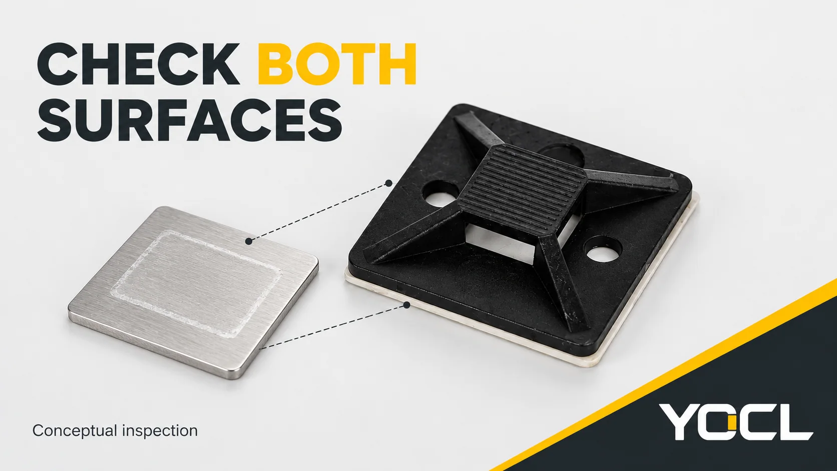
Adhesive cable tie mounts fall off when the bonded attachment cannot sustain the actual load and exposure. The weak region may be at the installation surface, within the adhesive/backing system, at the mount-to-backing interface, or in a coating or the plastic base itself. Surface contamination, an unsuitable material combination, an incomplete application process and sustained or edge-lifting loads are different possibilities—not interchangeable diagnoses.
Before re-sticking the base, preserve it and inspect both separated surfaces. Where a loose bundle could reach live parts, moving machinery or hot surfaces, have responsible personnel make the equipment and cable route safe first. Internal electrical work needs the appropriate isolation and competent personnel; the UK Health and Safety Executive’s HSG85 guidance, pages 20–22, explains the dead-working safety boundary.
Key Takeaways
- Keep the detached mount and photograph its underside and matching surface before cleaning.
- Residue, lifted coating, sliding and broken plastic point to different checks; appearance alone does not prove the root cause.
- Verify instructions for the actual backing and surface, including application conditions and time before loading. There is no universal waiting period or cleaner.
- A replacement needs a justified surface, process and mounting duty. A stronger cable tie cannot qualify a failed adhesive joint.
Find the apparent separation region first
Mark the mount’s original orientation and the direction of the bundle’s pull. Record whether the base lifted at one edge, moved across the surface or detached suddenly. Retain packaging and batch identification where available. Do not pull neighboring mounts off to reproduce the failure; that introduces another load and may damage a functioning cable route.
The following is a diagnostic framework for observations, not a laboratory failure classification. The National Physical Laboratory’s surface-bonding guide, particularly pages 7–9 and 93, provides the relevant surface and failure terminology. Thin residues can be hard to see, and several failure regions can occur together.
| What remains after separation? | What to check | What the observation can mean | Next action |
|---|---|---|---|
| Backing remains on the mount; the panel looks largely clean | Photograph both faces; identify the actual coating/polymer, preparation and backing | Apparent release near the surface interface; a clean-looking face does not prove it was uncontaminated | Review the backing-to-surface combination and application record |
| Backing remains on the panel; the plastic base separates from it | Preserve the base underside and retained backing; confirm original or replacement tape and any rework | The base-to-backing attachment needs investigation | Ask the supplier to assess the retained parts before selecting replacement backing or a new base |
| Torn backing or adhesive-like residue appears on both faces | Record tearing, displacement and the load/exposure history | A split within the backing/adhesive system is possible; residue alone does not establish the precise mechanism | Review sustained duty and environmental suitability with the supplier |
| Paint, coating or surface material comes away with the mount | Inspect the corresponding bare or damaged patch | The surface layer itself may have failed | Resolve the substrate/coating condition; stronger adhesive alone does not repair that layer |
| Plastic is cracked while the backing remains attached | Inspect the bridge, ribs and tie contact points without disturbing the cable route | The base body failed; this is a different branch from surface release | Replace damaged parts through the approved arrangement and review mechanical fit and duty |
| Only one edge has lifted, or the base has shifted | Record bundle direction, movement, contact footprint and installation orientation | Uneven contact or a load that opens an edge needs investigation | Assess the layout and attachment under the actual service direction before replacing |
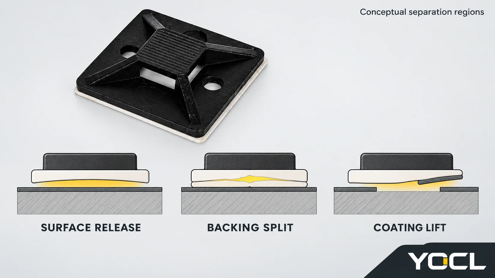
The cable tie mounts overview explains the component interfaces. For a fallen base, the useful next step is identifying which interface or material needs investigation.
Match the failure timing to the missing evidence
It would not stay in place during assembly
Start with the installation record: was the correct liner removed, was the intended backing present, and did the base make contact across its intended footprint? Check for dirt, oil, fingerprints, moisture, surface texture or curvature. Record observations before cleaning changes them.
NPL’s guide identifies contamination and weak surface layers as bonding concerns, while stressing that preparation depends on the substrate and adhesive. “Clean the panel” therefore needs a defined method for the actual coating or polymer. Do not prescribe a solvent, primer or sanding process from the mount’s nylon material alone. Such treatment may damage the receiving surface or electrical equipment.
For example, YOCL HT self-adhesive mounts are declared as adhesive-backed nylon 66 bases. Their current public page does not identify the backing chemistry or provide a substrate-specific preparation and application schedule. Obtain those details for the supplied configuration rather than assuming every backing uses the same process.
Check the supplied packaging for storage, shelf-life and traceability instructions too. Keep the batch reference and storage history for the review; appearance alone cannot establish whether the backing is still suitable for use.
It held initially, then released after the bundle was fitted
Reconstruct the sequence between bonding and loading. Request the specified application temperature, pressing method, time before load and permissible handling for the exact backing. Compare these requirements with what happened. A room-temperature photograph taken afterward does not establish the temperature of the surface when the mount was applied.
Do not turn a generic “wait overnight” recommendation into a corrective action. Without the relevant instructions, neither immediate loading nor a particular delay is established as acceptable. Also check whether installing or tightening the tie moved the base, opened one edge or forced it against a curved surface.
Where the record is incomplete, label that uncertainty. It is a reason to obtain process instructions and qualify a replacement assembly, not proof that the installer or adhesive was at fault.
It slid or detached after time in service
Record sustained bundle load, movement, vibration, temperature changes, moisture and cleaning exposure. Include a recent route change or service operation: the attachment may now be carrying a different duty from the original arrangement.
NPL’s guide, section 6.2, explains that short-term bond strength does not establish durability under sustained loading, and that temperature and humidity matter to that assessment. A quick hand tug therefore cannot establish a long-term mounting capacity. Sliding is a clue to investigate time-dependent behavior, not a field measurement of creep strength.
Preserve the installation history rather than simply fitting a larger base. YOCL’s HT footprint dimensions describe geometry; the public record does not assign an installed working load to those sizes.
Review how the cable loads the attachment
Look at the route with the cable safely secured. Is the base keeping a harness in position, or is it carrying sustained weight? Does a bend spring back against the fixing? Can opening a door, moving a machine axis or servicing the harness repeatedly lift an edge? Record the direction and movement, not just bundle diameter.
These questions identify the duty that replacement evidence must cover. They do not establish a universal allowance. Adding more bases also changes load sharing; do not divide bundle weight equally among them without a justified arrangement.
UL Solutions’ positioning-device application guide, page 3 of the linked guide, separates cable-tie loop strength from fixing-device mechanical strength. It also distinguishes adhesive used only to locate a device before mechanical fastening from adhesive used as the main attachment. Confirm which role is intended in your assembly. Neither a strong strap nor the presence of a screw hole establishes the adhesive joint’s capacity.
Do not over-tighten the tie to compensate for a loose mount. Review the base, strap, bundle and attachment as an assembly, with the intended support or positioning duty explicitly stated.
Choose a corrective action before fitting another mount
| Finding | Appropriate response | What must be established before return to duty |
|---|---|---|
| A documented preparation/application requirement was missed; the surface and duty are otherwise qualified | Replace the affected attachment using the approved process | Correct materials, receiving-surface condition, application record and required loading delay |
| Paint or another weak layer detached | Repair or reassess that surface through the equipment/coating procedure | A suitable receiving surface, rather than a new bond to the same weak layer |
| Backing, base or bond condition is damaged or uncertain | Preserve evidence and request a replacement/recovery decision | Whether reuse or replacement backing is permitted, and the identity of the resulting assembly |
| Required duty or exposure is outside the documented adhesive arrangement | Review the attachment design | An attachment suitable for the load, direction, duration and environment, plus permission for any modification |
| Failure recurs without a resolved cause | Escalate with the retained sample and installation record | The unresolved material, process or duty question; repeated re-sticking is not verification |
Do not assume a detached backing can be pressed back into service. Adding superglue, stacking tape, changing to an unspecified backing or driving a screw through a convenient hole creates a different arrangement. None has an established capacity merely because it feels secure.
If a design review concludes that mechanical fixing is appropriate, use the adhesive versus screw-mounted base comparison for that separate choice. Permission to drill, the receiving structure and the complete fixing still need confirmation. A screw is not a diagnosis of why the original bond failed.
Verify the correction against the original duty
Record the evidence and the specific change before the replacement is loaded. A useful corrective-action record includes:
- Mount model, backing identity and batch details where available.
- Receiving material or coating, surface condition and photographs of both separated faces.
- Application conditions and process, installation date and time before loading.
- Bundle route, attachment role, load direction, movement and service exposure.
- Failure timing, observed separation region, confirmed finding and unresolved questions.
- Approved correction, verification method, acceptance criteria and responsible person.
Use manufacturer- or equipment-approved checks for the intended assembly. An improvised destructive pull on an installed bundle can damage cables and creates a different load case. Define the relevant observation conditions and duration for the application; a brief unloaded check cannot close a sustained-load problem. Where environmental exposure was implicated, a dry bench observation alone is insufficient evidence that it has been addressed.
For a replacement review, send the retained evidence and this record through the YOCL cable tie mounts range. State whether the unresolved question concerns the surface, supplied backing, application process or mounting duty so the next discussion can identify the needed documentation.
Related reading: comparing clips and clamps for serviceable cable retention.
References
- UK Health and Safety Executive, Electricity at work: Safe working practices (HSG85), third edition, 2013, pp. 20–22—UK dead-working guidance.
- National Physical Laboratory, Surface testing for bonding, Measurement Good Practice Guide 77, issue 2, February 2025, pp. 7–9, 58–61 and 93—surface assessment, bond-test limits, sustained loading and failure terminology.
- YOCL product information, HT Self-Adhesive Cable Tie Mounts—declared backing/base construction, dimensions and original exterior image; reviewed November 2, 2026.
- UL Solutions, Cable Ties for Cable Management of Electrical Installations, linked positioning-device application guide, p. 3—fixing strength and adhesive roles; no YOCL product approval inferred.