
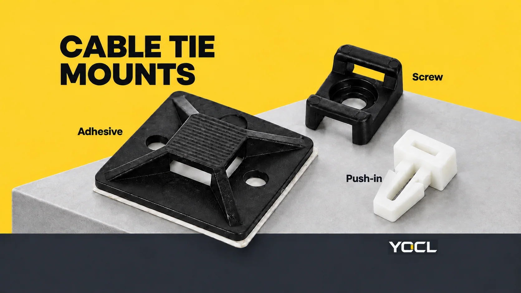
A cable tie mount is a separate base that anchors a cable tie to a surface. Adhesive bases bond to the substrate, screw bases attach through a fastener, and push-in bases retain in a specified panel hole. The tie holds the bundle; the mount and its attachment establish the fixing point.
The names cable tie base, tie mount and mounting base often describe this same separate component. A mounting cable tie combines the strap with a fixing feature; it is a different form, available in YOCL’s mounting cable tie range.
Follow the attachment from bundle to surface
Think of the assembly as a chain: cable bundle → cable tie → mount → adhesive, fastener or panel fixing → installation surface.
Each link answers a different question. Will the tie pass through the mount? Will the mount attach to the actual panel? What performance is documented for that attachment? A larger base or stronger tie resolves only part of the assembly.
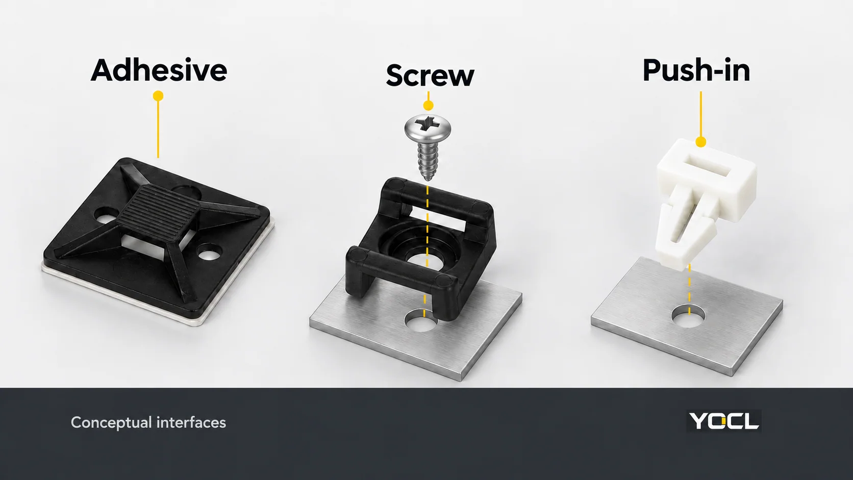
The three main fixing routes can be recognized by their physical interface:
| Base type | How it attaches | Key interface to identify |
|---|---|---|
| Adhesive | A bonded layer joins the base to the surface | Adhesive system, substrate and available bonding footprint |
| Screw | A fastener secures the base to the mounting structure | Fixing-hole geometry, compatible fastener and receiving surface |
| Push-in | A retaining feature engages a prepared panel hole | Hole diameter, supported panel thickness and retention geometry |
Some bases offer more than one fixing feature. Identify the intended attachment for the selected model rather than deciding from its outline alone.
Adhesive bases: distinguish backing from separately applied adhesive
Self-adhesive backing
A self-adhesive base carries its bonding layer beneath the body, usually protected by a removable cover. This provides a mounting route where drilling is restricted, provided the adhesive is suitable for the actual surface and duty.
YOCL HT self-adhesive mounts use adhesive-backed PA66 nylon bases. The published HT-20, HT-25, HT-30 and HT-40 footprints are respectively 20 × 20, 25 × 25, 30 × 30 and 40 × 40 mm. These dimensions describe space occupied by the base; they are not mounting-load ratings.
Evaluate the actual contact surface: bare metal, a particular paint coating or a polymer are different bonding substrates. Surface condition and texture also belong in the assessment. The UK National Physical Laboratory’s surface-testing guide abstract identifies substrate preparation, roughness, wettability and absorbency as bonding considerations, with assessment selected for the materials, process, loading and service conditions.
For a pre-backed mount, obtain its adhesive-specific preparation, application-temperature and load-before-use instructions. A generic waiting time or cleaning solvent cannot establish suitability for every backing and surface.
Paste or liquid adhesive mounts
An adhesive mount can also require a separately applied adhesive. YOCL PMB5 is described as a paste- or liquid-adhesive mount with a base intended for uneven surfaces and geometry that engages with cured adhesive. Its record also identifies hot-melt use.
That construction needs an appropriate adhesive/substrate combination and the corresponding processing instructions. The phrase “adhesive base” alone does not tell you whether a product arrives ready to peel and stick or needs a separate bonding process.
An adhesive can additionally hold a base in position while a mechanical fixing is installed. UL Solutions’ positioning-device guide distinguishes this positioning role from adhesive serving as the main securement. Verify which role is intended before treating a backing as the completed fixing.
Screw bases: match the mount and the receiving structure
A screw-fixed mount provides a hole or fixing feature through which a fastener attaches the body to a surface. The surface must provide the appropriate receiving arrangement, such as a documented threaded connection or other specified fixing.
YOCL HC saddle mounts use a separate cable tie and a screw-fixed nylon saddle. The central fixing hole and tie openings have different jobs: the fastener attaches the saddle, while the tie passes through the openings to retain the bundle.
The HC-1 drawing labels T = 5 mm for the tie-slot opening and B = 3 mm for the central fixing-hole dimension. The catalogue does not assign a screw size. A hole dimension is therefore a fit input, not permission to specify an M3 screw, a tightening torque or an engagement depth.
For the chosen assembly, confirm the screw/head fit, receiving material, available clearance and fixing instructions together. Screw attachment provides a mechanical connection, but its performance still depends on the complete fixing arrangement.
Push-in bases: the hole and panel thickness both matter
A push-in mount uses a retaining feature that enters a prepared hole and engages the panel. Arrowhead and other retention geometries have their own dimensional requirements; “push-in” is a fixing family, not a universal hole specification.
YOCL HSS-102158PA provides a useful concrete example:
| Published model field | HSS-102158PA value | What it describes |
|---|---|---|
| Hole diameter | 6.35 mm | The mounting hole |
| Panel thickness | 3.3–3.4 mm | The specified panel fit |
| Maximum tie width | 5.0 mm | The separate cable tie passing through the cradle |
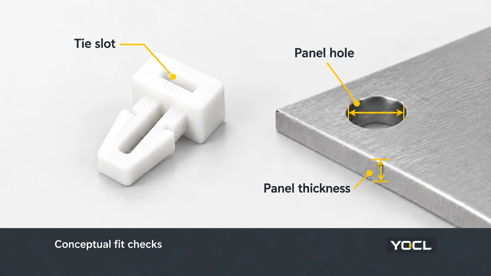
These are three independent fits. A 5 mm tie width does not imply a 5 mm panel hole, and a matching hole alone does not establish compatibility with a much thinner or thicker panel.
Use the specified model’s drawing and instructions for the hole, panel and retention arrangement. Removal and reuse also require model evidence; a push-in fixing should not be assumed to have a releasable mechanism.
Tie-slot fit remains a separate check
Once the surface attachment is identified, match the cable tie to the base. Check the accepted tie width, opening clearance, routing direction and room for the locking head. The assembled path through the base also affects the tie length needed around the bundle.
Read dimension symbols against the relevant drawing. The HT record identifies T as an opening dimension, not the mount thickness. HC uses T for its tie opening and B for its fixing hole. A letter reused across two drawings does not establish the same physical meaning.
Material, temperature and exposure requirements belong to the selected configuration. For outdoor duty, obtain the relevant environmental declaration; selecting a black-looking base is not a substitute for checking the specified material and exposure suitability.
Tie strength, mount strength and support duty are different
UL Solutions’ application guide, derived from UL 62275, distinguishes loop tensile strength of the cable tie from mechanical strength of the fixing device. The tie value alone does not establish a mount’s pull-out performance or long-term static load capacity.
The guide also separates securing a cable in position from supporting its weight. Where primary support is required, suitability must cover the intended cable, tie, fixing device, hardware and installation requirements. A routing base cannot be assigned a universal working load from its footprint or appearance.
For a specified mounting duty, request the applicable strength information with its test or declaration conditions and installation arrangement. A general nylon material classification is also a different claim: the HT and HC records explicitly distinguish their stated UL 94 V-2 material classification from a finished-product UL listing.
Choose the next resource by the interface still unresolved
| Your question | Next resource or information |
|---|---|
| Which separate base forms are available? | YOCL cable tie mounts catalogue |
| Is the adhesive pre-applied or separately applied? | HT or PMB5 model record, then the adhesive/substrate instructions |
| Which fastener fits the saddle? | HC drawing and the specified receiving/fixing arrangement |
| Will an arrowhead base fit the panel? | HSS model’s hole diameter, panel-thickness range and retention instructions |
| Will the tie pass through and close around the bundle? | Accepted tie width, opening geometry, routing and head clearance |
For a model review, send the surface material or coating, fixing method, hole and panel dimensions where relevant, tie width, bundle size, mounting duty, service conditions and quantity. This gives YOCL the information needed to identify the base and the documentation required for its attachment.
Related reading: See why adhesive cable tie mounts fall off and adhesive versus screw-mounted bases.
Related reading: cable clip and clamp retention options.
References
- YOCL ELECTRIC — Mounting Cable Ties; first-party description of integrated bundling and mounting features.
- YOCL ELECTRIC — HT Self-Adhesive Cable Tie Mounts; first-party backing, dimensions and material-classification information.
- National Physical Laboratory — Surface testing for bonding, Measurement Good Practice Guide 77, Issue 2 (2025); public abstract only.
- YOCL ELECTRIC — PMB5 Paste Adhesive Cable Tie Mount; first-party construction and bonding-selection information.
- UL Solutions — Application Guide: Cable Ties for Cable Management of Electrical Installations, linked positioning-device guide identified as updated July 2026; fixing devices, adhesives, strength and support distinctions.
- YOCL ELECTRIC — HC Saddle Cable Tie Mounts; first-party fixing and drawing-label information.
- YOCL ELECTRIC — HSS-102158PA Arrowhead Fixing Base; first-party hole, panel-thickness and maximum tie-width values.