
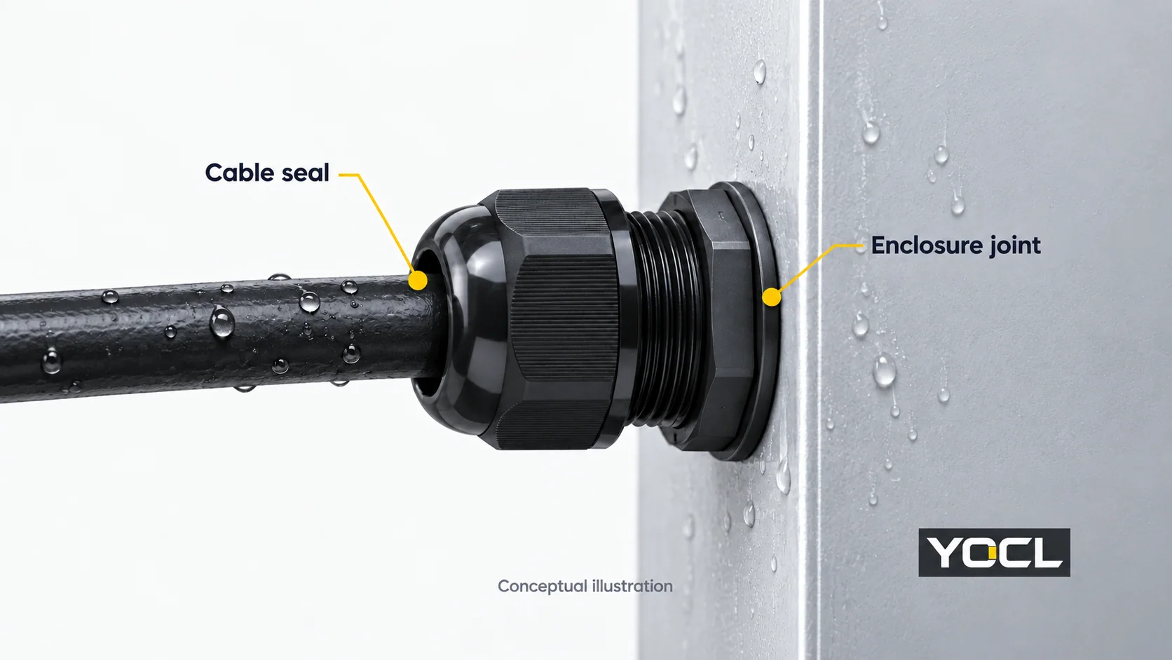
A cable gland can leak because the cable does not fit its seal, a sealing surface is damaged, the gland-to-enclosure joint is incorrect, or an adapter adds an unverified entry path. Water found near the gland can also come from another opening, the cable itself, or condensation. Locate the moisture path before tightening or replacing anything.
If water has reached electrical equipment, keep people clear and arrange safe isolation from a safe location. A competent person must secure the isolation and verify the equipment is dead before opening the enclosure or disturbing the cable entry. UK regulator HSE’s electrical-safety guidance supports these precautions; apply the isolation and inspection requirements for the actual installation.
Key takeaways
- Check the cable seal and the enclosure joint separately. Tightening one does not verify the other.
- Match the actual cable outside diameter and shape to the exact gland and insert.
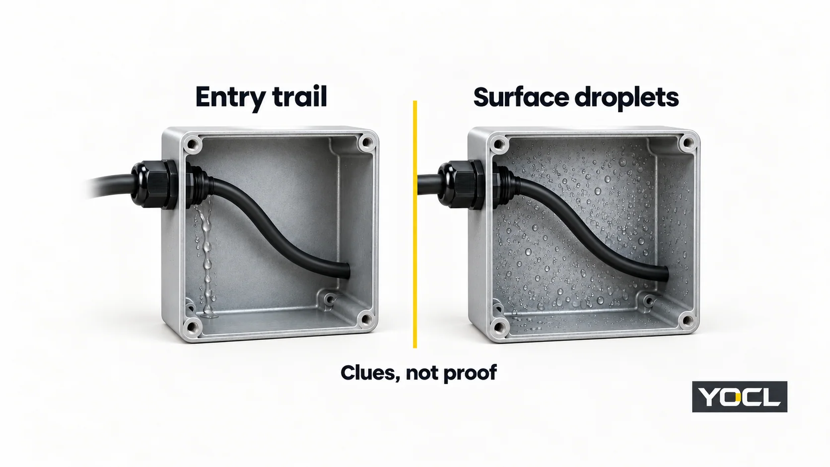
- Record water trails and component positions before disassembly; a low drip point may be downstream of the entry.
- A dry-looking enclosure after repair does not establish that water-affected equipment is safe to energize.
Locate the moisture path before changing a part
Once safe access is established, photograph the cable entry, inside wall, lid, adjacent openings and any water marks. Record whether the event followed rain, cleaning, cable replacement, movement or a temperature change. Distinguish an existing stain from observed fresh moisture.
Start with the visible route and test the hypothesis against the product drawing. Water can run along surfaces before collecting, so the wettest part is not necessarily where it entered. A photograph taken after opening the lid cannot by itself distinguish earlier ingress from water introduced during opening.
Preserving the initial condition helps the investigation. NASA’s general seal-failure guidance explains that removal and disassembly can change stresses or obscure evidence. Its discussion concerns fluid seals generally, rather than cable-gland certification; the relevant lesson here is to document the condition before disturbing it (NASA, seal failure analysis, p. 7-11).
| Observed clue | Suspected path | Check after safe isolation | What the finding means | Next action |
|---|---|---|---|---|
| A local trail follows the jacket through the entry | Cable-to-seal interface | Compare cable diameter, profile, jacket condition and insert identity with the exact model data | An out-of-range cable or unsuitable profile is a proven mismatch; a trail alone is only a clue | Correct the specification or damaged component, then verify the assembled entry |
| Moisture starts around the mounting hole behind the gland shoulder | Enclosure joint | Compare the entry drawing, sealing arrangement, surface and fixing stack | A missing specified seal or incorrect mounting geometry identifies a joint defect | Restore the documented joint; do not compensate by tightening the cable cap |
| A wet line begins at an adapter or reducer | One of the added joints | Identify both mating interfaces and the required seals or thread treatment | Matching thread names alone leaves the sealing arrangement unverified | Check each joint against its permitted configuration |
| A crack, distortion or displaced seal is visible | Body or sealing-component damage | Record the damage and review assembly, loading and exposure history | The part needs assessment; its appearance alone does not establish why it failed | Replace affected parts as instructed and resolve the cause |
| Droplets cover a cold wall or lid without a clear entry trail | Possible condensation | Review humidity, surface temperature and event timing, alongside other openings | Condensation remains plausible; it can coexist with a liquid leak | Investigate moisture and thermal conditions before prescribing a new gland |
| Water emerges from a cable’s cut end or between its internal elements | Possible upstream or cable-interior route | Record the emergence point and refer cable construction and upstream exposure to the cable supplier | A jacket seal alone has not resolved the route | Escalate the cable/termination assessment |
These branches are diagnostic hypotheses, not stand-alone acceptance tests. Do not spray, flood, dye-test or pressurize an installed electrical assembly to see where it leaks. Any ingress verification needs an equipment-specific method, controlled conditions and competent responsibility.
For the component roles behind these checks, see the cable gland types and parts overview.
Check the cable seal against the exact model
The thread can match while the cable range fails
Identify the full gland code and insert. Read the permitted cable range, then compare it with the cable manufacturer’s dimensional limits and a suitable measurement of the jacket at the sealing location. Do not compress a soft jacket with the measuring tool or measure an unrelated section of cable.
YOCL’s one-piece Metric nylon cable-gland table shows why an M20 marking is insufficient:
| YOCL catalogue model | Entry thread | Declared cable range | Screen for a hypothetical 13.0–13.4 mm cable |
|---|---|---|---|
| VO-NLM20A-UN | M20 × 1.5 | 6–12.5 mm | Outside the published range |
| VO-NLM20B-UN | M20 × 1.5 | 8.5–14 mm | Within the published range; remaining checks still apply |
The cable interval is illustrative; the model values are YOCL catalogue declarations. The first model has a dimensional mismatch. The second passes this cable-range screen only—it is not thereby approved for the enclosure, exposure or complete sealing arrangement. Tightening cannot turn the first row into the second.
If the installed gland or insert cannot be identified, record the fit as unresolved. Use the cable gland selection guide for the wider dimensional review once the suspect interface is known.
Check shape, cable count and the jacket surface
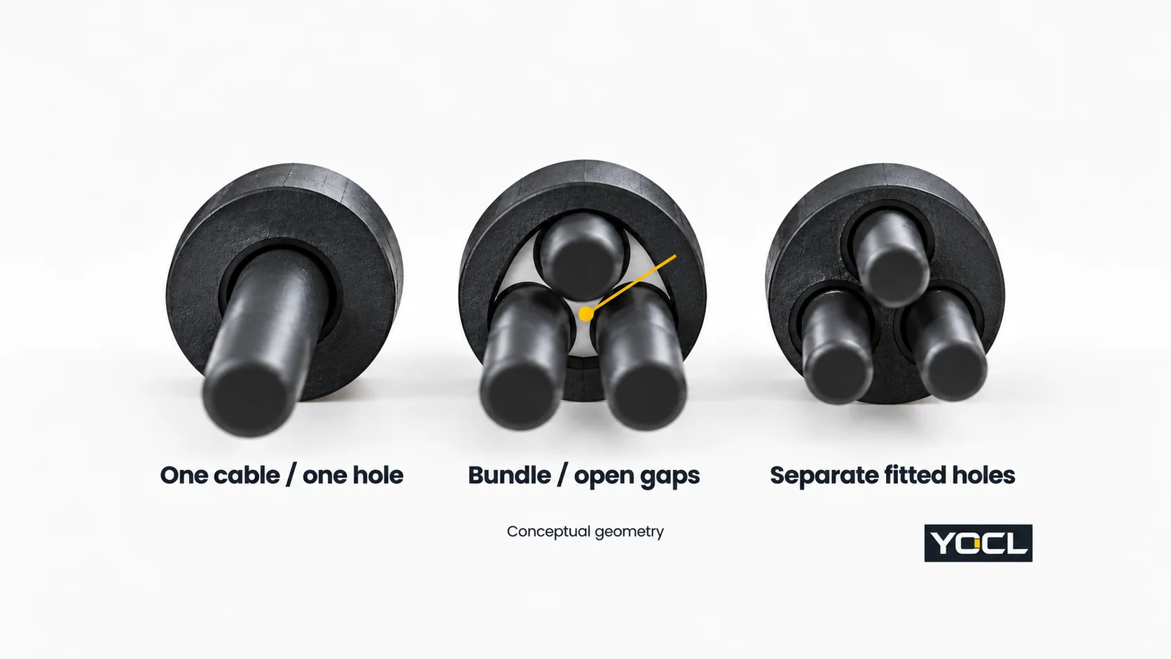
A round single-cable seal should not be assumed to close the spaces between several bundled cables. IEC 62444 distinguishes a single-cable opening from a multi-opening seal with separate cable passages (public preview, definitions 3.11–3.12).
YOCL’s multi-hole and flat-hole nylon gland series lists separate configurations and individual cable ranges. Check each occupied hole independently. A vacant hole also needs the closure permitted for that exact insert; a spare screw or improvised filler is not a documented substitute. Flat and oval cables need an appropriate profile specification.
Inspect the intended contact area for cuts, flattened sections, dirt or previous compression damage. Review whether the jacket, seal and cleaning chemicals are compatible. NASA’s general seal-failure analysis includes damage, contamination, dimensional errors, misalignment and chemical deterioration among potential mechanisms; none can be diagnosed from age alone.
If leakage began after the cable was moved, review the supported route and any side loading or displacement. Do not pull a connected cable as an improvised retention test. Correct the routing or support problem together with any damaged seal; replacing a part without addressing the loading leaves the cause open.
Inspect the enclosure joint independently
The cable-side cap acts on the cable seal. The body shoulder, entry seal and fixing arrangement address a different boundary at the enclosure. A cable may fit correctly while water enters around the mounting hole.
Compare the assembly with the exact drawing:
- Entry: Is it a tapped hole or a clearance hole, and is its thread or hole geometry compatible with the selected gland?
- Sealing arrangement: Does the drawing require an O-ring, sealing washer, a specified thread treatment or another arrangement? Is the correct component present in the instructed position?
- Surface: Is the sealing face damaged, contaminated, uneven or obstructed where the specified seal must contact it?
- Fixing: Does the available thread length accommodate the wall and specified accessory stack? Are the components seated as instructed?
A locknut normally provides mechanical fixing; its presence alone does not demonstrate entry sealing. Equally, adding an arbitrary washer does not prove that an incorrect hole, damaged thread or unsuitable mating face has been repaired. Assess the defect against the enclosure and gland documentation.
If thread identity is uncertain, use the Metric, PG and NPT comparison. Do not force a close-looking thread into the entry or treat tape as a thread conversion.
Follow every joint through an adapter or reducer
An adapter adds interfaces to the inspection. Record the enclosure-to-adapter joint and the adapter-to-gland joint separately, including thread identities, permitted sealing method and mounting space. Confirm that the whole stack is acceptable to the equipment design.
The cable gland accessories range separates fixing, thread conversion, closure and bonding functions. A shroud, locknut or earth tag should not be credited with a sealing function merely because it covers or surrounds the joint.
Recheck exposure when a previously dry entry starts leaking
Record changes since the last satisfactory condition: a smaller replacement cable, a moved cable route, a new detergent, hotter cleaning, prolonged wetting, sunlight or mechanical impact. Compare those conditions with the exact body, seal and assembly documentation. The investigation needs the actual chemical and exposure conditions, not a generic request for a “waterproof” replacement.
An ingress protection (IP) marking is not a universal permission for every cleaning or immersion condition. IEC 60529 classifies enclosure protection. Request evidence for the actual exposure and assembled configuration, including cable, entry and accessories; a component label alone does not settle that question.
IEC 62444’s public preview identifies supplier documentation such as sealing range, entry dimensions and installation torque where applicable. Its type-test provisions use glands assembled to the supplier’s instructions. These support a practical rule: use the exact instructions and obtain missing data rather than guessing a torque or borrowing it from another series (IEC 62444:2010, clauses 5.2 and 7.3). Referencing the standard does not certify the installed YOCL part.
Rule out condensation and routes that bypass the local seal
Condensation deserves a separate branch when droplets form over cold internal surfaces or follow temperature cycles without a localized trail. The physical condition is a surface at or below the dew point of nearby moist air; the US National Weather Service’s dew-point explanation illustrates this with a chilled surface. The enclosure’s bulk air temperature alone may miss the colder surface.
IEC 60529’s public scope preview, clause 1 treats protection against condensation-related moisture as a matter for the relevant product standard. An IP designation alone therefore does not establish a condensation-free enclosure. Continue with why condensation forms inside a sealed enclosure when that branch fits the evidence.
Also inspect the wider route: lid seals, unused openings, adjacent fittings and the cable’s upstream exposure. Water arriving at the local gland on the outside of a cable is different from water emerging from inside the cable. Record which is observed. Where the cable-interior route is suspected, obtain cable and termination guidance; do not assume a tighter jacket seal will address it.
Decide whether to correct, replace or escalate
Correct a documented assembly error when the exact parts are identifiable, their condition is acceptable and the manufacturer provides a permitted correction. That could involve restoring the specified seal or fixing arrangement. The correction must address the recorded defect.
Re-specify the entry when the cable range, profile, entry geometry or exposure does not match. Replacing the gland with another of the same thread size repeats the problem if the cable-side mismatch remains.
Replace affected components as instructed when the body is cracked, threads are damaged, seals are torn or distorted, or the manufacturer does not permit reuse. Preserve the suspect parts for investigation. Do not mix similar-looking caps, seals and bodies from different series without documented compatibility.
Escalate when the source remains unknown, leakage recurs, cable interiors or electrical components have become wet, or hazardous-area protection or bonding may be affected. Equipment for explosive atmospheres (Ex) needs a competent application-specific review. A successful local sealing correction does not approve water-affected terminals, protective devices or electronics for reuse.
Avoid packing a cable seal with tape, heat shrink or general-purpose silicone to alter its diameter. Use thread sealant or other compounds only where the exact equipment and entry instructions specify them. A visually filled gap is not evidence of a qualified repair.
Record the correction and the evidence for return to service
Close the job with a record that another person can review:
| Record | Information to retain |
|---|---|
| Original condition | Event timing, inside/outside photographs, water route and affected equipment |
| Exact configuration | Gland and insert codes; cable diameter/profile; enclosure entry; adapters and seals |
| Confirmed defect | Measured mismatch, missing specified part, damage, or unresolved hypothesis |
| Corrective change | Parts replaced or assembly corrected, with the relevant instruction reference |
| Verification | Equipment-specific checks, conditions, acceptance criteria, responsible person and results |
| Release decision | Water-damage assessment, required electrical inspection/testing and authorization before energization |
A hose check or absence of a fresh drip is not an IP certification. If the verification method or acceptance criteria are missing, keep the result open for manufacturer or engineering review. Observation after an approved return to service can reveal recurrence; it does not replace the checks needed to authorize that return.
For help matching replacement gland components, send the recorded cable dimensions, entry drawing, exposure details and photographs through the YOCL cable gland range. Ask for the proposed model, compatible accessories and installation documentation together.
References
- Health and Safety Executive, Electrical safety: frequently asked questions, safe isolation and competent inspection guidance; UK context.
- NASA, Parts, Materials, and Processes Experience Summary, 1973, section “Guide to Failure Analysis of Fluid Sealing Devices,” printed p. 7-11. General seal mechanisms and evidence preservation; not cable-gland qualification.
- YOCL ELECTRIC product information, One-Piece Nylon Cable Gland — Metric Thread, catalogue rows VO-NLM20A-UN and VO-NLM20B-UN, checked 23 October 2026.
- International Electrotechnical Commission, IEC 62444:2010 — Cable glands for electrical installations; public preview, definitions 3.11–3.12 and clauses 5.2/7.3. Only the public scope and preview were consulted.
- YOCL ELECTRIC product information, Multi-Hole & Flat-Hole Nylon Cable Gland, seal profiles and per-hole cable ranges, checked 23 October 2026.
- International Electrotechnical Commission, IEC 60529:1989+AMD1:1999+AMD2:2013 — Degrees of protection provided by enclosures (IP Code); public preview, clause 1, enclosure protection and condensation scope.
- US National Weather Service, Temperature — Dry Bulb/Wet Bulb/Dew Point, dew-point temperature and condensation on a chilled surface.