
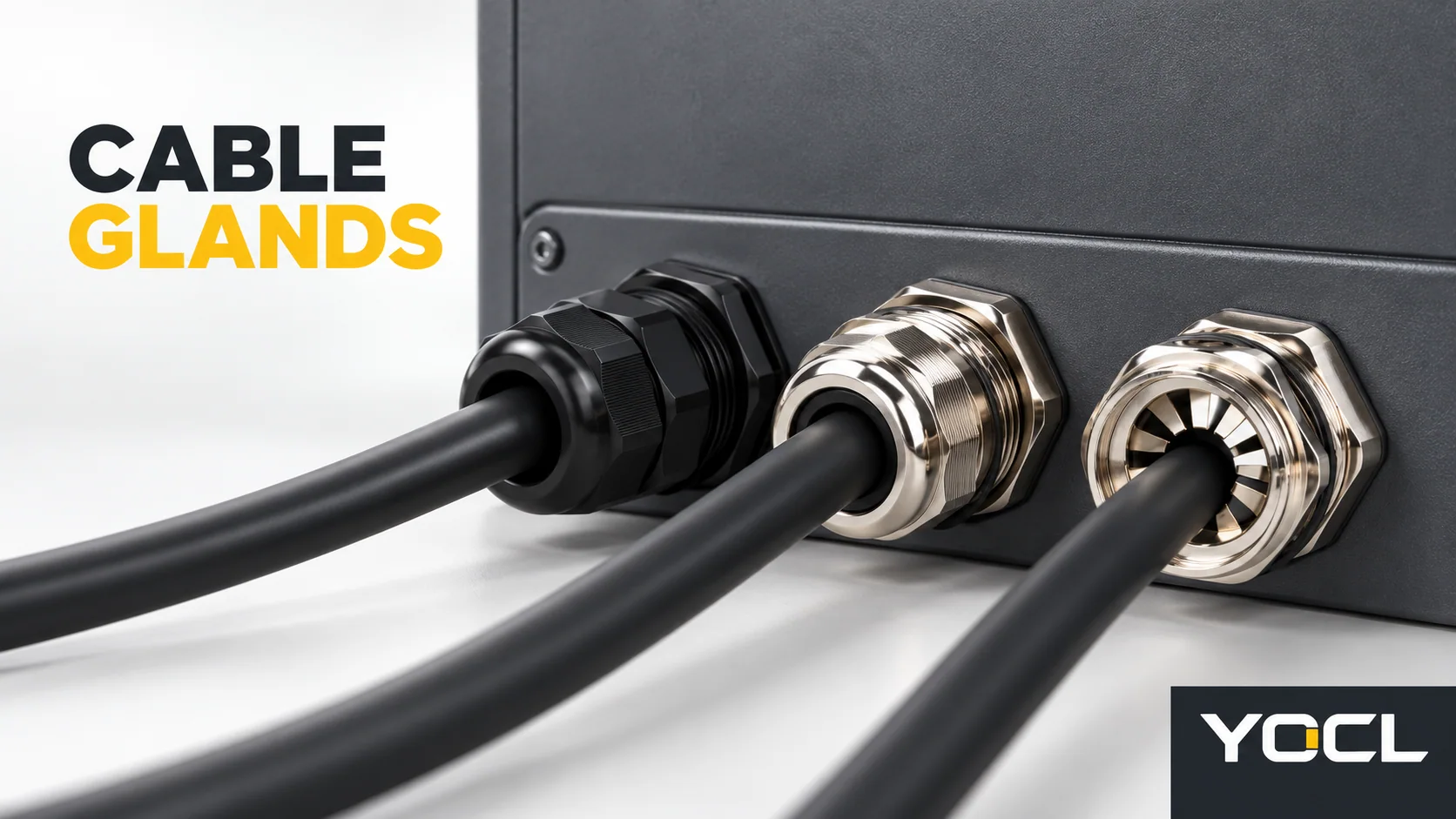
A cable gland is an enclosure-entry device that allows an insulated cable to pass through an enclosure or equipment wall while providing sealing and retention. It mounts through a compatible entry thread or clearance hole and normally closes around the cable jacket with a sealing or clamping arrangement. Some gland designs also provide strain relief, earthing or bonding, electromagnetic compatibility (EMC) contact, armour clamping, pressure equalization or hazardous-area functionality.
Those additional functions do not come from the name “cable gland” alone. They belong to the exact product design, cable construction, accessories and installed assembly. This guide builds the product map first, then routes the reader to the deeper page for sizing, thread identification, material choice or a specialized gland family.
Key takeaways
- A cable gland has a cable-side interface and an equipment-side interface.
- Sealing and cable retention are the basic functions; strain relief, EMC, armour bonding, venting and hazardous-area features are model-specific additions.
- The entry-thread designation is not the accepted cable diameter.
- A complete enclosure entry requires the gland, cable, enclosure thread or hole, seals and accessories to work together.
What a cable gland does at the enclosure boundary
The clearest way to understand a gland is to follow the cable through the enclosure wall. Outside the enclosure, the gland may support or guide the cable. At the enclosure wall, it provides a mounting interface. Around the cable jacket, its seal or clamping elements limit water and foreign-object entry and help hold the cable in position.
IEC 62444 defines the cable gland as a device that permits a cable, flexible cable or insulated conductor to enter an enclosure and provides sealing and retention. The same adopted-standard preview describes optional functions including earthing, bonding, insulation, cable guarding and strain relief (GSO IEC 62444:2025, §3.1). That definition is a useful boundary: the product family can include many constructions, but optional functions must be proved for the selected design.
For a panel builder or equipment manufacturer, the gland is also a transition between four objects:
- The cable jacket and construction outside the enclosure.
- The sealing or clamping elements acting on that cable.
- The body and entry thread connecting to the enclosure.
- The internal or external accessories needed for sealing, fixing, bonding or routing.
An apparently simple product therefore comprises more than a threaded body. The relevant parts change with the model.
The parts of a cable gland and what each interface must do
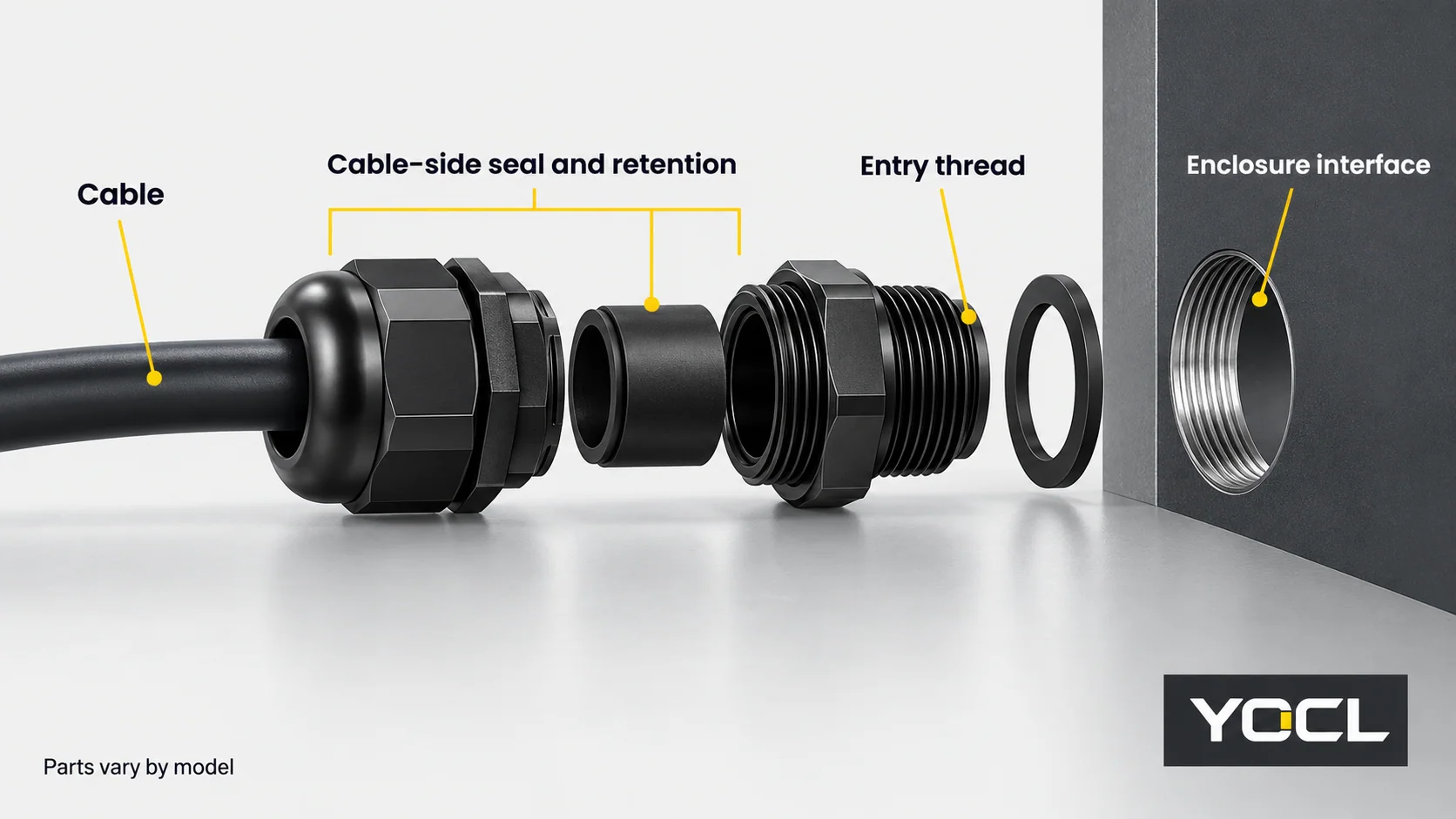
Supplier terminology varies, and one-piece designs can combine several functions in one moulded or machined body. Use the table as a functional map, then match the names and components in the exact drawing.
| Visible part or interface | Functional job | What the reader must verify |
|---|---|---|
| Cable-entry cap or compression nut | Acts on the sealing element and may transmit clamping force to the cable | Exact cable outside-diameter range and the model’s assembly method |
| Cable seal, grommet or clamping element | Limits entry around the jacket and contributes to cable retention | Cable profile, jacket material and the full diameter tolerance range |
| Body or dome | Houses the sealing/clamping geometry and connects the cable side to the entry side | Intended cable construction and whether the body form suits routing or space |
| Mounting thread | Attaches the gland to a threaded enclosure entry | Thread family, size, pitch, plate thickness and required engagement |
| Clearance-hole fixing | Mounts a gland through an unthreaded opening | Hole drawing, fixing method and the accessories specified for that arrangement |
| Enclosure seal, O-ring, washer or locknut | Closes or fixes the equipment-side interface where the product design requires it | Exact part, mounting surface, stack height and instructions |
| Optional contact or bonding part | Provides a designed connection to a shield, armour, enclosure or conductor path | The required electrical function and exact assembly evidence |
| Optional venting element | Permits controlled pressure equalization | Air-flow and sealing data, installation orientation and enclosure requirements |
The mounting thread and the cable acceptance range are separate fields. In the standard terminology, the gland size is the nominal diameter of the entry thread, not the diameter of the cable. The thread is the portion intended to connect to the enclosure or equipment (GSO IEC 62444:2025, §3.2–3.3). A product described as “M20” is therefore not automatically suitable for a 20 mm cable.
Cable-side sealing is not the same as cable retention
Two products can close around a cable yet provide different retention. The standard preview distinguishes cable retention, which limits displacement under static load, from cable anchorage, which addresses displacement under dynamic and torque loads (GSO IEC 62444:2025, §3.4–3.5). For catalogue readers, the practical point is simpler: “sealed” and “strain-relieved” are different claims unless the exact model documents the combination.
A sealing range also has two limits. The smallest cable in the production tolerance must not lie below the product’s minimum, and the largest must not exceed its maximum. Tightening an oversized or undersized cable until it looks closed does not create a documented fit. The complete selection process also accounts for the enclosure thread, plate thickness and accessories; those steps are covered in the YOCL cable gland selection guide.
This is why a cable’s conductor cross-section, AWG size or core count cannot replace its outside diameter when selecting a gland. A sealed multi-core cable and a smaller-diameter single-core cable may use different conductors but require their own jacket diameters and constructions.
The cable gland types most buyers need to distinguish
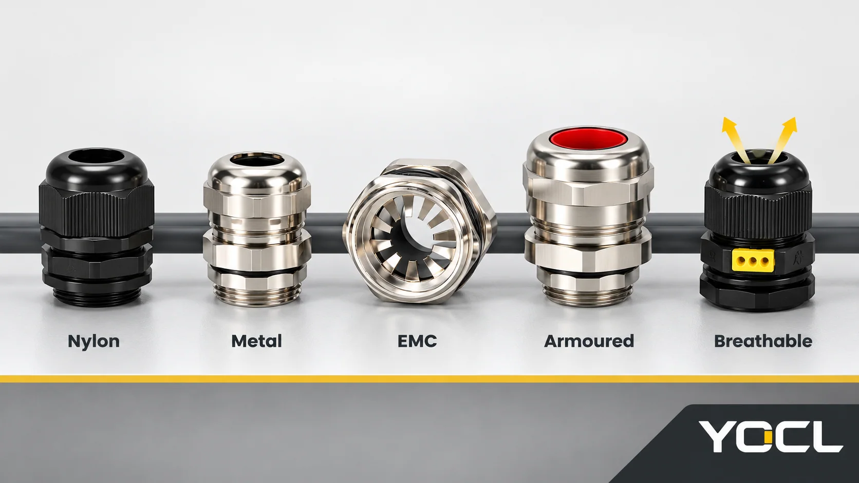
Cable glands are usually grouped by body construction, cable construction and required function. The table is a navigation map, not a universal recommendation chart. Branches can overlap: a metal gland may also be an EMC or armoured gland, while a breathable gland may use either metal or polymer construction.
| Product branch | Start here when the cable-entry task involves | YOCL family page | Deeper technical route |
|---|---|---|---|
| Nylon cable gland | A compatible polymer body, a conventional round cable and no required conductive or armour function | Nylon cable glands | Compare the body material using Nylon vs Brass Cable Glands |
| Metal or nickel-plated brass cable gland | Greater mechanical presence, a metal assembly or a designed earthing/bonding interface may be relevant | Metal cable glands | Confirm the alloy, finish, seal and required electrical path |
| EMC cable gland | A screened cable requires a designed shield-contact arrangement | EMC cable glands | A metal exterior alone does not prove EMC contact |
| Armoured cable gland | A cable has wire or tape armour that must be accommodated by the gland construction | Armoured cable glands | Check bedding, armour and outer-sheath dimensions for the exact model |
| Ex cable gland | The installation is in a classified hazardous area and requires the applicable protection concept | Ex cable glands | Use the equipment certificate, installation requirements and qualified review |
| Marine cable gland | The cable entry must address a declared shipboard, coastal or other marine service condition | Marine cable glands | Confirm the alloy/finish, seal and target-market evidence for the exact environment |
| Breathable cable gland | The design needs a documented pressure-equalization function in the cable entry | Breathable cable glands | Read What Is a Breathable Cable Gland? |
| Cable-gland accessories | The closing decision is a locknut, sealing washer, earth tag, thread adapter, reducer, shroud or screw cap | Cable gland accessories | Match each accessory to the exact gland, thread and assembly function |
Nylon and metal glands answer different starting questions
A nylon cable gland is generally the simpler starting point for a compatible plastic enclosure and an ordinary fixed, unarmoured cable when no conductive body function is required. Its lower mass and polymer construction can suit light-duty panels and equipment. That does not make all nylon compounds interchangeable or automatically suitable for prolonged UV, chemical or high-temperature exposure; the exact material and product data still govern.
A metal cable gland begins from a different physical context. Nickel-plated brass or another metal construction may be considered where the enclosure is metal, where mechanical duty or heat is part of the requirement, or where a designed earthing, bonding or screening path is needed. The words “brass” and “metal” do not prove those functions, and the finish, alloy, seal and contact arrangement still matter.
The full trade-off is a separate decision, so compare the two families in Nylon vs Brass Cable Glands. A material choice should follow the enclosure, cable construction, mechanical duty, exposure and required electrical function.
EMC and armoured glands add different cable functions
An EMC cable gland is relevant when a screened cable must make a designed contact through the gland. The product must provide the required contact geometry, and the enclosure assembly must complete the intended path. A shiny metal body, a visible clamp or the word “EMC” on the catalogue page does not establish continuity; the exact model, cable preparation and installation arrangement must support the function.
An armoured cable gland is used where the cable includes armour that the entry design must accommodate. Armour is a mechanical and sometimes electrical feature with its own dimensions and termination requirements. A gland that fits the cable’s outer jacket may still have the wrong inner seal or armour-entry arrangement. When ordering or replacing this product, supply the cable construction and the exact gland drawing rather than only the nominal cable size.
Keep EMC shield contact and armour termination as separate questions. A fine braided screen, a metallic tape layer and heavy steel armour wires do not share the same preparation or connection requirements.
Ex and marine glands add application-specific evidence
An Ex cable gland belongs to a hazardous-area application with a defined equipment protection concept, certificate and installation scope. The article cannot determine that scope from a photograph or a generic cable dimension. Route selection through the location classification, equipment documentation, applicable installation requirements and a competent reviewer; a family label is not approval for every Ex installation.
A marine cable gland begins from an application condition. “Marine” can imply salt exposure, moisture, washdown, vibration or a target-market approval requirement, but those are not identical. Verify the exact alloy and finish, seal compatibility, mounting arrangement and any project-standard or certification evidence demanded by the vessel or equipment.
These two families have less room for generic advice than nylon versus metal. Their value in the hub is to identify when the ordinary selection route must stop and become an application-specific review.
Breathable glands and accessories solve different closing problems
A breathable cable gland combines cable sealing with a controlled venting path. It can reduce pressure differences while still having its own airflow, protection and installation conditions. It is not a universal cure for condensation, and it should not be selected by the word “breathable” alone. The article What Is a Breathable Cable Gland? explains the separate sealing and pressure-equalization questions.
Cable-gland accessories finish or adapt an assembly. A locknut fixes a gland through a clearance hole. A sealing washer addresses the enclosure joint rather than the cable seal. A threaded adapter or reducer changes an interface. An earth tag or EMC locknut addresses a declared bonding function. Each accessory has a different job, and each must match the exact gland, enclosure and target assembly.
Do not use an accessory to hide a mismatched primary interface. An adapter may be valid when the gland and enclosure documentation allow the resulting arrangement; it does not make two thread systems dimensionally identical.
Thread families and application boundaries come next
After identifying the product branch, confirm the enclosure-entry interface. Metric, PG and NPT glands use different thread systems, and a close outside diameter does not establish interchangeability. Read the designation, mating drawing or verified measurement, then use Metric vs PG vs NPT Cable Gland Threads for the focused comparison.
The product’s ingress-protection claim also needs to be read in context. IEC 60529 classifies degrees of protection provided by enclosures (IEC 60529). A gland rating, cable range and enclosure rating are inputs to the assembly decision; they do not separately prove the completed enclosure entry. The cable seal, enclosure seal, thread or clearance-hole fixing, accessories and installation conditions must all be compatible.
This is equally true for EMC, bonding and hazardous-area claims. A complete product standard provides a construction and performance framework, but the exact model documentation and the installed configuration determine what can be claimed for the application.
Choose the next cable-gland resource by the decision you need to make
The term “cable gland” covers a family of distinct products. Use the desired decision to leave this hub at the right point.
| Your next decision | Continue with |
|---|---|
| Match a cable outside diameter, entry thread and mounting conditions | How to Choose a Cable Gland |
| Identify a Metric, PG or NPT entry | Metric vs PG vs NPT Cable Gland Threads |
| Compare nylon with nickel-plated brass construction | Nylon vs Brass Cable Glands |
| Understand a pressure-equalizing entry | What Is a Breathable Cable Gland? |
| Match a locknut, seal, adapter, reducer or bonding component | Cable gland accessories |
| Review available gland constructions and request a model match | YOCL cable glands |
When requesting a model, provide the cable part and outside-diameter range, cable construction, entry thread or hole drawing, enclosure material and thickness, exposure conditions and any required shield, armour, venting or hazardous-area function. Those inputs let the exact gland and accessories be checked as one cable-entry assembly.
Related reading: See cable clips and clamps explained.
References
- International Electrotechnical Commission, IEC 62444:2010 — Cable glands for electrical installations, official scope.
- GCC Standardization Organization, GSO IEC 62444:2025 — Cable glands for electrical installations, public preview, definitions §3.1–3.7.
- International Electrotechnical Commission, IEC 60529:1989+AMD1:1999+AMD2:2013 — Degrees of protection provided by enclosures (IP Code), official scope.
- YOCL ELECTRIC, Cable Glands Manufacturer and the linked current product-family pages, YOCL product information.