
Short Answer
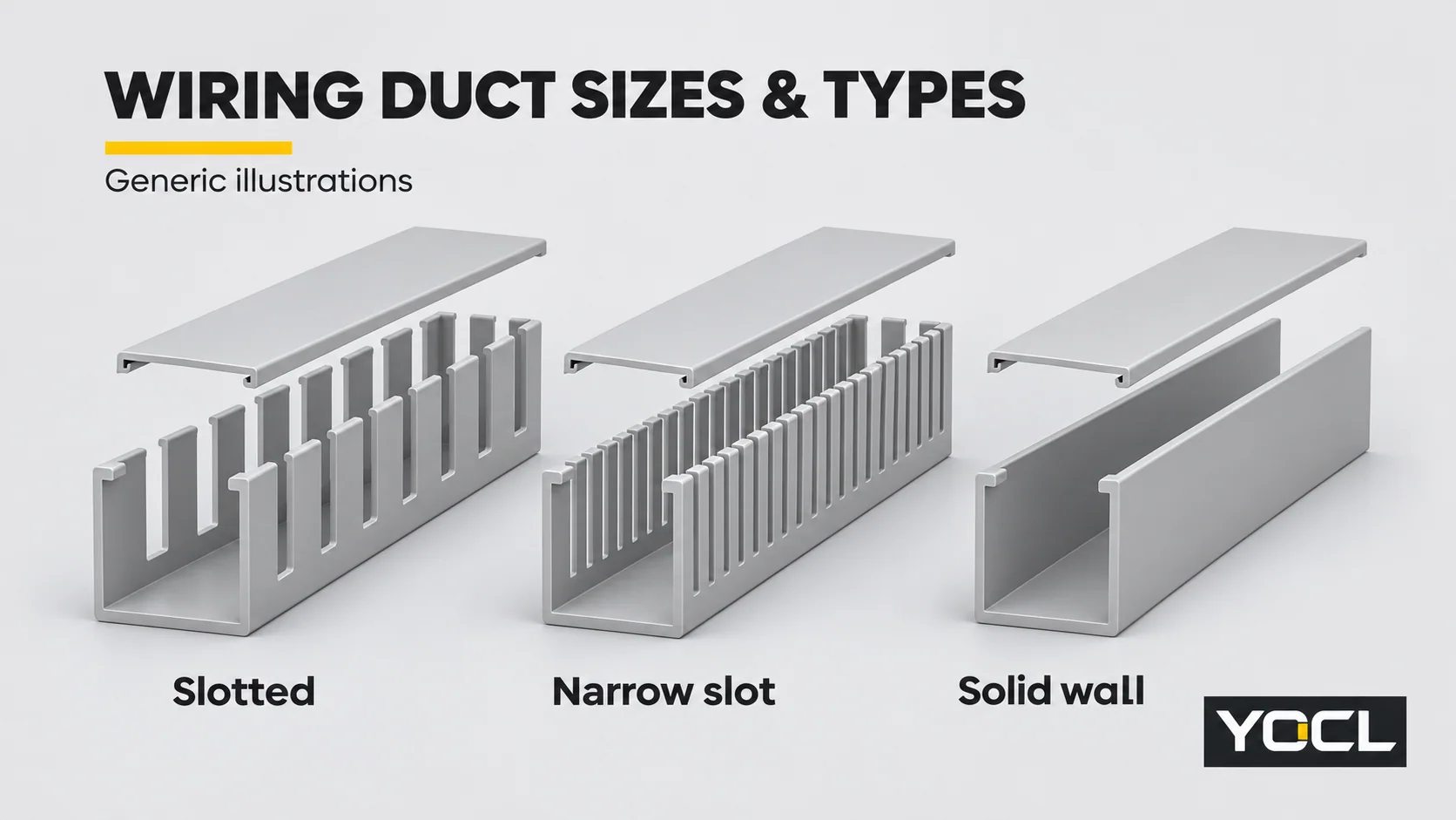
Wiring duct, also called panel cable trunking, organizes wires inside a control cabinet beneath a removable cover. Standard slotted duct suits frequent branch-outs, narrow-slot duct suits closely spaced small-wire exits, and solid-wall duct suits routes with fewer side exits. Start choosing wiring duct sizes by adding the cross-sectional areas calculated from each wire’s outside diameter over insulation, then compare that total with the duct’s usable internal area and your planning fill allowance.
This guide covers cabinet routing, not building raceway design. The official scope of IEC 61084-2-3 places slotted cable trunking inside cabinets and distinguishes it from conduit systems. The examples below are generic industry dimensions and design calculations; they are not YOCL product specifications or an offer of wiring duct.
1. Choose the type by the wire-exit pattern
The key distinction is how wires leave the channel to reach nearby equipment. Narrow-slot duct is a form of slotted duct, rather than a completely different containment system.
| Type | Suitable control-panel route | Main advantage | Tradeoff to check |
|---|---|---|---|
| Standard slotted / finger duct | General wiring beside terminal rows and devices with frequent branch-outs | Wires can leave through distributed side openings | Slot opening must accommodate the actual wire or group without forcing it against an edge |
| Narrow-slot / fine-finger duct | Dense control and signal wiring beside closely spaced terminals | More closely spaced exit opportunities help separate small branch wires | Narrow openings can obstruct larger cables, markers or groups; smaller slots do not create extra internal capacity |
| Solid-wall duct | A feeder route or enclosed run with few planned branch points | Continuous side walls contain the route without a row of open fingers | Side exits need suitable planned openings or fittings; changes are less convenient |
Use the actual exit geometry to choose between standard and narrow slots. A channel can have enough area for the main bundle yet lack a suitable opening where that bundle must branch out. Do not force a cable through a slot or remove fingers arbitrarily to rescue a poor layout.
A solid plastic wall is not, by itself, an electromagnetic shield or an environmental seal. If circuit separation is required, specify the applicable routing arrangement or verified partition system rather than assuming that a cover resolves it.
2. Compare standard metric wiring duct sizes
The following are common standard sizes in metric catalogues, stated here as width x height, W x H. “Standard sizes” means familiar nominal market sizes, not a claim that one standard mandates this exact series. These are not YOCL models, stock sizes or guaranteed internal dimensions.
| Nominal size, W x H | Width | Height | Relative cable-routing scale | Typical layout use |
|---|---|---|---|---|
| 25 x 25 mm | 25 mm | 25 mm | Small local wire group | Short branch beside a compact device |
| 40 x 40 mm | 40 mm | 40 mm | Modest control-wire route | A local terminal-row channel |
| 40 x 60 mm | 40 mm | 60 mm | Greater depth within the same nominal width | A busier route where backplate width is limited |
| 60 x 60 mm | 60 mm | 60 mm | Medium main route or mixed branch groups | Distribution between equipment rows |
| 80 x 80 mm | 80 mm | 80 mm | Larger common route | A main vertical or horizontal wiring channel |
| 100 x 100 mm | 100 mm | 100 mm | Large route requiring substantial panel space | A heavily populated cabinet’s main channel |
The routing descriptions are qualitative layout examples, not wire-count capacities. A count without wire outside diameters, slot details and usable-area data would be misleading. Also verify the supplier’s dimension order: a listing written as height x width must not be read as W x H.
Width, height and slot pitch do different jobs
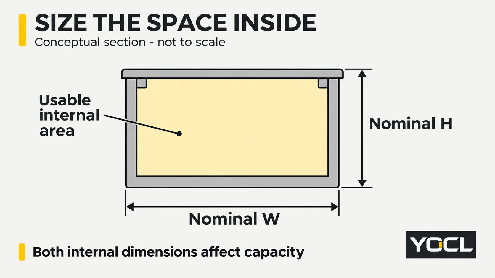
Width consumes backplate space; height projects toward the cabinet door. Both internal dimensions determine capacity. Increasing height can add room without widening the route, but may obstruct the cover, equipment or door clearance. Increasing width can provide more side-by-side routing room, but takes space away from equipment and service access.
Exit density depends chiefly on the slots along the duct’s length: their pitch, opening width and finger geometry. A wider duct is not automatically a duct with more exit points. Choose the cross-section for the bundle and the slot pattern for the branch-outs.
Use the supplier’s usable-area data or internal drawing for the capacity check. Nominal W x H describes an envelope; walls, cover features, dividers and retained accessories can reduce the space available for wires.
3. Calculate the required area, then test the next size
Add the insulated wire areas for each route segment
Use the cable or wire datasheet’s outside diameter, not its copper cross-section. For a round insulated wire:
Wire area = pi x outside diameter squared / 4
For several wire groups:
Total occupied area = sum of (wire quantity x pi x outside diameter squared / 4)
Use one consistent unit throughout. For a multicore cable, count the complete cable’s outside envelope; do not add its internal cores again. For a non-round cable, use its documented envelope rather than forcing it into the round-wire formula.
Calculate the busiest segment, including wires that pass through it before branching off. A lightly populated end section cannot justify undersizing the shared route nearer the cable entry.
Use about 50% as a declared planning assumption
A common starting point is to plan around 50% occupied cross-sectional area. In this guide, that is a design rule of thumb, not a universal mandatory value from EN 50085, UL 1565 or every installation code. An applicable code, equipment standard, manufacturer instruction or project specification may impose a specific limit; follow that requirement where it applies.
With a selected planning fraction:
Required usable duct area = total occupied wire area / planning fill fraction
The unused area accommodates imperfect packing, crossings and access. It is not automatically a promise that the same number of wires can be added later. Include known spare circuits in the wire schedule before calculating, and keep room for dressing the exits and replacing the cover.
A physical fill calculation also does not establish cable current capacity. The IET’s discussion of conduit and trunking capacity distinguishes containment capacity from conductor sizing, which also depends on installation conditions and grouping.
Worked example: when the next taller duct makes sense
Illustrative assumptions only: the following wires and internal dimensions are invented for arithmetic, not taken from YOCL or any commercial duct specification.
| Wire group | Quantity | Assumed outside diameter | Combined occupied area |
|---|---|---|---|
| Small control wires | 40 | 3 mm | About 282.7 mm2 |
| Larger insulated wires | 12 | 5 mm | About 235.6 mm2 |
| Current total | 52 | Mixed | About 518.4 mm2 |
| Planned additional control wires | 10 | 3 mm | About 70.7 mm2 |
| Planned total | 62 | Mixed | About 589.0 mm2 |
At the example’s 50% planning fill, the planned route needs approximately 1,178.1 mm2 of usable internal area, calculated before rounding the wire-group results.
Now assume a hypothetical 40 x 40 mm candidate has an unobstructed internal rectangle of 34 x 34 mm, or 1,156 mm2. Its planned fill would be about 51.0%, so it misses the chosen planning target.
A hypothetical 40 x 60 mm candidate with an internal rectangle of 34 x 54 mm, or 1,836 mm2, would have a planned fill of about 32.1%. It is the next taller candidate in this example while retaining the same nominal backplate width. Select it only if its extra projection, slot openings, cover access and cable bends also fit.
This is the logic behind “choose the next size up”: resolve a failed usable-area or routing check with a suitable larger candidate. It does not mean adding an arbitrary safety factor or using nominal W x H as if it were internal area. If height is constrained, a wider route or a different layout may be the better change.
4. Select PVC or a documented halogen-free / LSZH system
PVC is a conventional material for cabinet wiring duct. Consider it where the equipment specification permits it and the particular product’s documented properties suit the installation. Material name alone does not establish fire behaviour, service conditions or compliance.
Consider a documented halogen-free system where the project seeks to limit halogen-related combustion effects. If reduced smoke is also required, ask for evidence of that property separately. Halogen-free and low-smoke are not interchangeable claims. Low-smoke zero-halogen, or LSZH, combines two requirements; a halogen-free label alone does not establish both. UL Solutions explains this distinction in its HF and LSHF cable-certification guidance. That cable guidance does not certify a duct product.
| Project context | What to resolve in the duct specification |
|---|---|
| Rail transport | The vehicle or infrastructure project’s material, smoke and fire requirements; obtain evidence for the actual duct and accessories |
| Public buildings | Requirements relevant to occupied spaces and evacuation routes, rather than assuming every cabinet needs the same polymer |
| Data centres | Smoke and corrosive-combustion concerns around sensitive equipment, together with the facility’s actual specification |
| General industrial cabinet | Permitted material, documented fire behaviour and installation conditions for the equipment being built |
These are reasons to investigate the material requirement, not blanket claims that a named industry always mandates LSZH.
Use standards references precisely. BS EN 50085-2-3 concerns slotted trunking intended for cabinets. The published scope of UL 1565, Positioning Devices, includes non-raceway wiring ducts and excludes evaluation of any mechanical protection or electrical insulation those devices provide. Neither standard’s name is a fire rating, a low-smoke declaration or proof that a particular YOCL product is certified.
For procurement, request the actual duct system’s applicable test evidence and declared classification, including compatible covers and accessories. Do not transfer a resin statement, cable certificate or another manufacturer’s approval to the finished duct system.
5. Plan mounting, accessories and terminal access together
Screw fixing versus DIN rail mounting
A duct beside a DIN rail is not necessarily mounted on that rail. For screw-fixed duct, use the base openings, fasteners and panel attachment specified for the duct system. Keep fastener heads and the mounting arrangement from obstructing the wire route.
Use DIN rail mounting only when the duct or a documented adapter is designed for the particular rail interface. A generic channel does not become clip-on duct because it is placed above a rail. Confirm retention, orientation and the extra depth introduced by the mounting system.
Use DIN Rails Explained for the mounting interface and TS35 DIN Rail Dimensions for the rail section. The duct decision here is whether the supported assembly fits the available cabinet space.
Covers, dividers and retainers
- Covers: match the actual duct series and width. Allow access to remove and refit them after the adjacent devices are installed. A cover that must be forced over the wires signals a problem to resolve.
- Dividers: use compatible parts where the routing plan needs separate compartments. Recalculate each compartment’s available area. A plastic divider alone does not establish electromagnetic shielding or every required electrical separation.
- Wire retainers: compatible retainers hold wires in place while the cover is removed. Account for any space they occupy; they are not automatically cable strain relief.
Cut cleanly and preserve service space
Follow the duct system’s cutting instructions. Cut the base and cover to the required lengths with a suitable tool, remove sharp edges and clear all chips before wiring. Make deliberate exit openings without leaving damaged fingers or burrs against the insulation. Do cutting and drilling away from exposed conductors and equipment wherever practical.
Locate the duct so wires can leave toward terminals without a sharp turn or obstructed tool access. Leave room for the actual prepared wire ends, markers, terminal operation and cover removal. There is no universal duct-to-terminal gap that can replace those geometry checks.
Keep terminal selection in How to Choose a DIN Rail Terminal Block, and use How to Organize DIN Rail Terminal Blocks with Jumpers and End Stops for the row arrangement. Check the resulting cable paths against the duct layout instead of repeating those hardware decisions.
6. Know when conduit, hose or simpler supports are preferable
Exposed outdoor routing: the cabinet wiring duct discussed here is intended inside an enclosure. For outdoor cable routes, select conduit or a suitable protective hose system with fittings documented for the actual exposure. Check sunlight, water, mechanical damage, support and entry sealing as a complete system. A solid wall and snap-on cover do not make indoor duct weatherproof.
Curved or moving routes: conduit or flexible hose can suit a route that cannot be served by straight cabinet channels. For a moving door or repeated flexing, verify the cable and protective system’s movement suitability and bend requirements; flexibility by itself is not a repeated-motion rating.
A small number of wires: a complete duct run may consume unnecessary panel space. Properly supported ties and mounts can be more proportionate where the route needs neither continuous containment nor the duct’s branch-out arrangement. Use Cable Tie Mounts Explained to resolve the attachment interface.
For conduit-to-enclosure interfaces, review YOCL’s published Conduit & Hose Connectors category. These are connectors; the category is not a wiring duct range or evidence that every mating conduit is suitable outdoors.
For the surrounding cabinet components, use the Control Panels & Cabinets application page to reach the relevant DIN rails, DIN rail terminal blocks and cable tie mounts. Contact YOCL with the panel layout and required components for an enquiry about those published product families.
FAQ
What sizes do wiring ducts come in?
Common nominal metric wiring duct sizes include 25 x 25, 40 x 40, 40 x 60, 60 x 60, 80 x 80 and 100 x 100 mm, expressed here as width x height. These are generic standard market sizes, not YOCL stock specifications or one universally mandated series. Check the supplier’s dimension order, usable internal area and cover fit before choosing a size.
How do I calculate the wiring duct size I need?
For each route segment, add the areas of the wires calculated from their insulated outside diameters: quantity x pi x diameter squared / 4. Include planned spare wires, then divide by the selected planning fill fraction. About 50% is a useful design rule of thumb in this guide, not a universal code requirement. Choose a duct with sufficient documented usable area, then verify exits, bends, mounting and cover access.
Slotted or solid wiring duct: which is better for a control panel?
Slotted duct is usually the more convenient choice beside terminal rows because wires can branch through distributed side openings. Narrow-slot duct helps organize closely spaced small-wire exits. Solid-wall duct suits routes with fewer planned side exits, but requires suitable openings or fittings at those exits. Choose by the actual branch pattern and cable geometry; solid plastic walls do not automatically provide shielding or weather protection.
When should I choose halogen-free wiring duct over PVC?
Choose a documented halogen-free duct system when the project’s material and combustion requirements call for it, such as in some rail, public-building or data-centre installations. If low smoke is also required, obtain evidence for that separately: halogen-free alone does not mean LSZH. Confirm the actual duct, cover and accessories against the applicable project specification; do not infer their performance from a polymer name.
Can wiring duct be used outdoors?
The control-panel wiring duct discussed here is intended for use inside cabinets. For exposed outdoor routing, use conduit or a suitable protective hose system documented for the environment, together with compatible fittings. Review YOCL’s Conduit & Hose Connectors category for the enclosure interface, and verify the complete route’s exposure and sealing requirements. Indoor wiring duct and its cover are not substitutes for an outdoor conduit system.
Related reading: choosing cable identification markers.
References
- IEC – IEC 61084-2-3:2017+AMD1:2024, consolidated version, official public scope for slotted cable trunking installed inside cabinets; full test clauses are not reproduced here.
- IET, Michael Peace – The history of cable capacities for conduit and trunking, November 2021; containment capacity and conductor-sizing context.
- UL Solutions – Halogen Free and Low Smoke Halogen Free Cable Certification, separate smoke and halogen concepts; cable context, not duct certification.
- BSI – BS EN 50085-2-3:2010, official catalogue scope for cabinet slotted trunking.
- UL Standards & Engagement – UL 1565, Positioning Devices, published scope including non-raceway wiring ducts and its stated exclusions.