
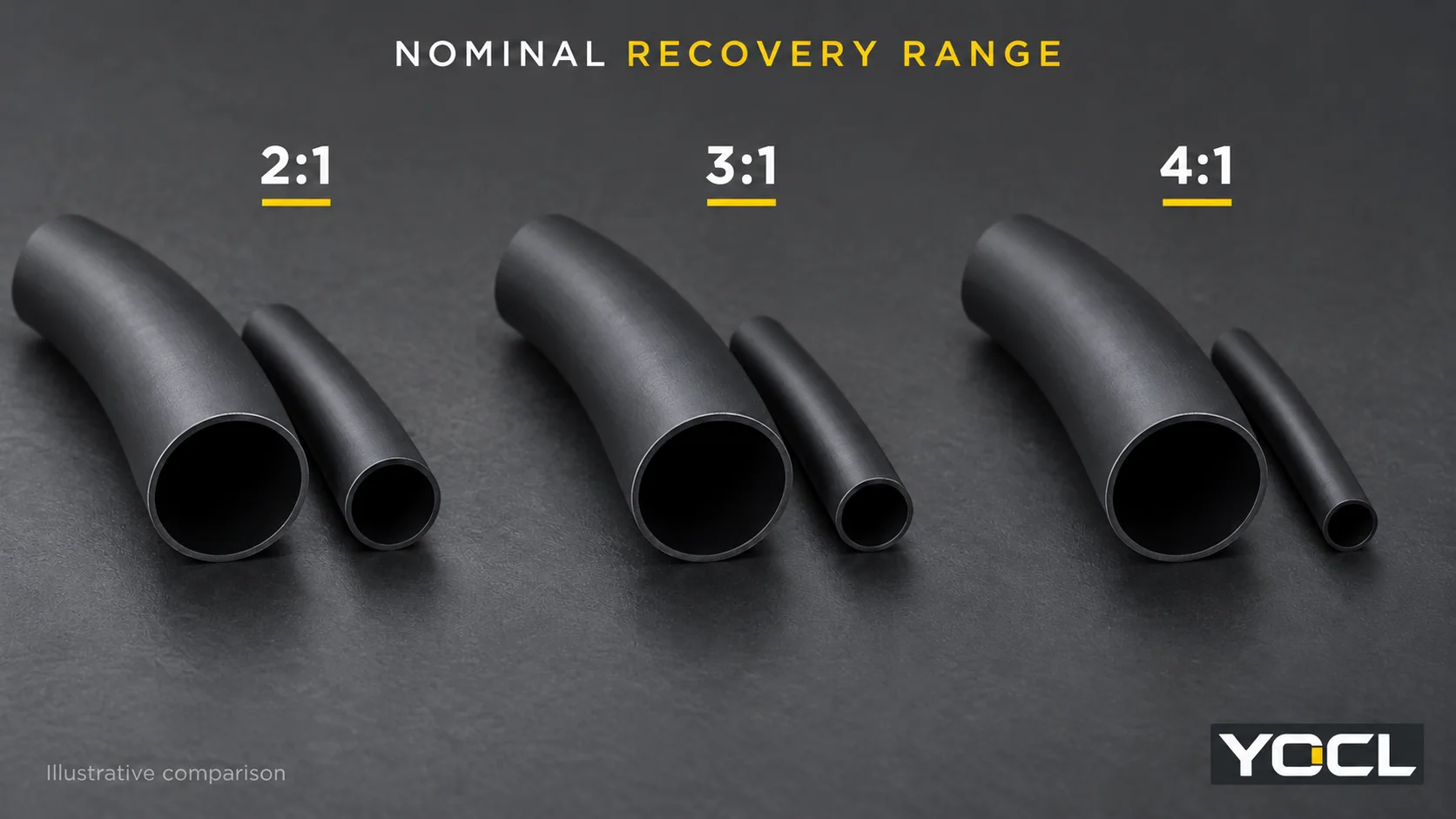
Choose the shrink ratio from the diameter transition the tubing must bridge. Its supplied bore must clear the largest feature, and its freely recovered bore must be smaller than the narrowest surface it needs to grip. A suitable 2:1 size can already complete that job. Consider 3:1 or 4:1 when the actual dimensions require a wider recovery range.
Higher ratio alone does not provide adhesive, a sealed connection or a higher electrical rating. Compare the geometry first, then check the exact product’s construction and duty.
Compare 2:1, 3:1 and 4:1 on the same geometry
Shrink ratio describes the nominal relationship between expanded inside diameter (ID) and freely recovered ID. For idealized arithmetic:
Free-recovery ID = expanded ID ÷ ratio number
With the same hypothetical 15 mm expanded bore, 2:1 gives 7.5 mm, 3:1 gives 5 mm, and 4:1 gives 3.75 mm. These are illustrative endpoints without an internal object restricting recovery, rather than guaranteed dimensions of three catalogue products. Ratio describes diameter recovery; it does not divide the cut length or identify the number of walls. The heat-shrink tubing terminology guide explains those separate fields.
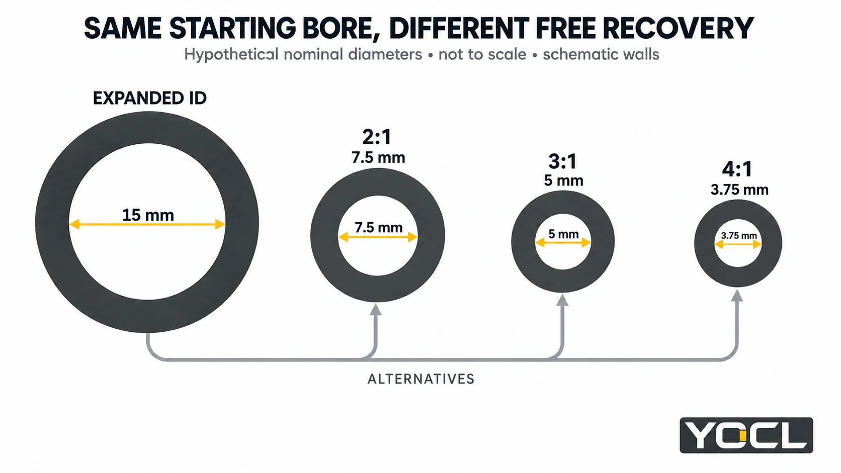
Now hold the largest round feature the tubing must pass over at 13 mm outside diameter (OD). Change only the smallest round surface where it must land. All three hypothetical sleeves start with the same 15 mm bore, so the comparison isolates their recovery range.
| Smallest landing OD | 2:1: free ID 7.5 mm | 3:1: free ID 5 mm | 4:1: free ID 3.75 mm | Sufficient ratio under these assumptions |
|---|---|---|---|---|
| 9 mm | Below landing OD | Below landing OD | Below landing OD | All three; 2:1 already suffices geometrically |
| 6 mm | Too large | Below landing OD | Below landing OD | 3:1 or 4:1; 3:1 already suffices geometrically |
| 4.5 mm | Too large | Too large | Below landing OD | 4:1 only |
| 3 mm | Too large | Too large | Too large | None of these three candidates |
This is a controlled hypothetical comparison, not an approved size list. The 2 mm difference between the assumed expanded bore and pass-over OD is an example gap, not a recommended clearance. Actual tolerances, installation allowance and permitted application range remain to be checked.
The last row matters: even 4:1 can be insufficient. A higher ratio extends the nominal range, but no label guarantees fit across every transition. Conversely, the first row gives no dimensional reason to reject 2:1 simply because 4:1 is available.
Turn a ratio candidate into an exact tubing size
For round parts and open-ended tubing, check both limits from one exact size row:
- Minimum supplied ID > largest pass-over OD
- Maximum freely recovered ID < smallest landing OD
NASA’s KSC-E-165 Revision F, §3.8.1.1.1(a) uses this expanded-larger/recovered-smaller principle within Kennedy Space Center electrical ground-support-equipment fabrication. It supports the dimensional relationship, without approving a YOCL product or assembly.
Retain the table’s minimum, maximum and ± signs, component tolerances and specified application allowance. Equality supplies no assured margin. A model’s stated application range may further restrict the usable diameters, even where the preliminary inequalities pass.
If you increase the supplied size to clear a connector, recheck the recovered limit of that larger row. Changing the first diameter can also change the second. Use the heat shrink tubing size chart for the full lookup and limit conventions.
Free recovery is different from installed fit
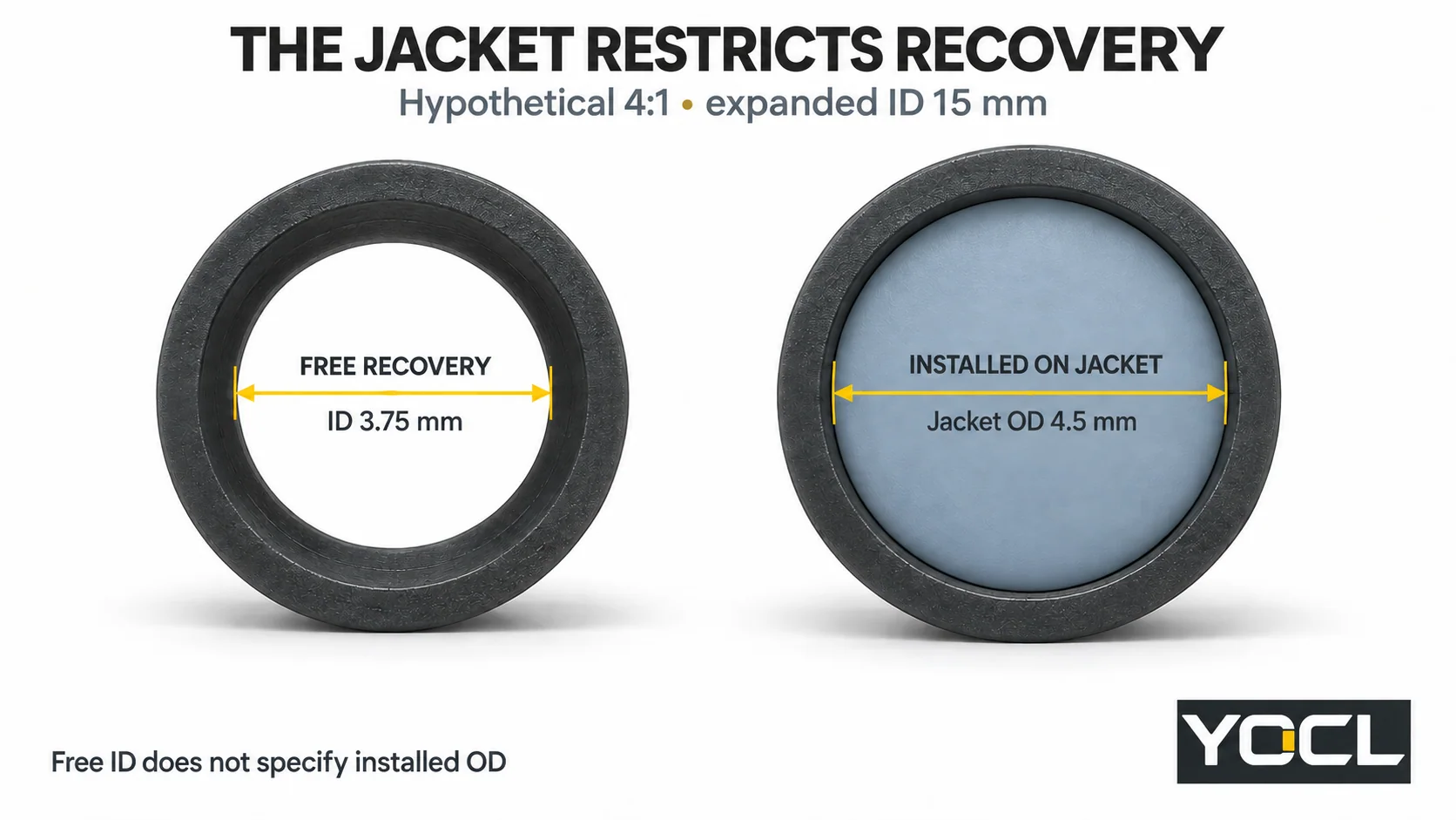
A sleeve installed over a cable stops contracting against the surface inside it. In the hypothetical 4:1 example, a 4.5 mm jacket prevents the bore reaching its empty 3.75 mm endpoint. The endpoint therefore does not specify installed ID, outside diameter or wall thickness.
For a sleeve spanning several surfaces, check the smallest required landing as well as the largest feature it crosses. Irregular connectors, flat busbars, bundles and branches need their actual envelope and contact geometry reviewed; one round OD cannot describe every gap or valley.
A real YOCL 3:1 vs 4:1 comparison
The 3:1 Zero-Halogen single-wall product and 4:1 Zero-Halogen single-wall product offer a useful same-construction comparison. Both declare no internal adhesive. Their 20 mm supplied-bore entries have different recovered limits:
| Published field | 3:1 single wall | 4:1 single wall |
|---|---|---|
| Size entry | 20.0/6.7 mm | 20.0/5.0 mm |
| Minimum supplied ID | 20.0 mm | ≥20.0 mm |
| Maximum ID after recovery | 6.7 mm | ≤5.0 mm |
| Internal adhesive | None | None |
These are manufacturer declarations from the respective dimension tables, checked 9 October 2026. The 3:1 page establishes minimum and maximum through its column headings; the 4:1 page also prints the inequalities in each row.
For hypothetical 18 mm pass-over and 6 mm landing dimensions, both supplied minima clear the large feature. The 3:1 row’s 6.7 mm recovered maximum does not establish contraction below 6 mm; the 4:1 row’s 5.0 mm maximum does. That makes the latter a dimensional candidate, still subject to allowance and application review. It does not prove a sealed joint.
Keep the published 6.7 mm limit. Replacing it with 20 ÷ 3 would substitute nominal arithmetic for the actual declaration.
Check construction and duty alongside the ratio
The unlined 4:1 example shows why ratio cannot identify adhesive. Where a bonded interface is required, select an appropriate lined product and assess compatibility, contact geometry and sealing evidence. Use the single-wall versus dual-wall comparison for that decision.
Compare actual wall fields and their measurement states rather than assuming 4:1 is thicker or stronger. Also check coverage and declared longitudinal change, permitted recovery conditions, service temperature, electrical duty and required environmental evidence for the exact grade. Diameter ratio supplies none of those values.
A tight exterior or visible adhesive at an end cannot by itself verify the complete sealing interface. If an installed sleeve is already loose, damaged or has an unverified seal, the heat-shrink failure guide addresses that separate investigation.
Make the final choice from the products that pass
Keep 2:1 in consideration when its exact size meets both fit checks and the required function. Move to 3:1 or 4:1 when their documented recovery range solves a transition the lower-ratio candidate cannot cover. If several products pass, compare their construction, installed space, process and duty. If none passes, revise the exact size or connection arrangement instead of assuming extra heat will deliver extra recovery.
For a YOCL size review, provide the largest pass-over dimension, smallest landing dimension, required coverage, jacket material and intended duty through the heat-shrink tubing product range. Request the matching size limits, permitted application range and installation information so the final selection identifies a product and size, not just “4:1 heat shrink.”
References
- NASA Kennedy Space Center — KSC-E-165 Revision F, 20 December 2021, Electrical Ground Support Equipment Fabrication, Specification for. §3.8.1.1.1(a), printed page 59; scoped expanded/recovered size principle.
- YOCL product information — 3:1 Zero-Halogen Single-Wall Heat Shrink Tubing. 20.0/6.7 mm row, dimension headings and absence of adhesive; checked 9 October 2026.
- YOCL product information — 4:1 Zero-Halogen Single-Wall Heat Shrink Tubing. 20.0/5.0 mm row, supplied/recovered bounds and absence of adhesive; checked 9 October 2026.