
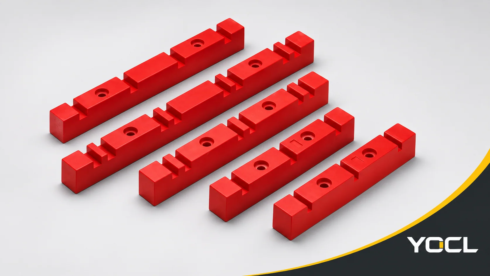
A busbar clamp and a standoff insulator fix bars by different logics. A grooved clamp supports and positions several parallel bars as a group, at the pitch built into its body. A standoff uses threaded metal inserts to fix an individual bar at a chosen point and height while providing electrical separation from the mounting panel. Choose according to the bar layout and fixing task; an assembly may need both.
For a clamp, start with the bar thickness that must seat in the groove, then read the complete model drawing for length, groove spacing and mounting features. For a standoff, identify the individual support points and required height. These interfaces explain the choice more usefully than a general claim that either component is better.
Two fixing logics: a positioned group or individual points
The important difference is what each component locates. A grooved body establishes positions across a row of bars. A standoff establishes a support point beneath a particular bar. In YOCL’s catalogue, the DL and EL busbar clamp pages describe a support-and-positioning function; the standoff comparison concerns an insulating body with threaded metal inserts.
| Layout question | Grooved busbar clamp | Standoff insulator |
|---|---|---|
| What does the component locate? | Several parallel bars through grooves in a shared body | An individual bar at a selected fixing point |
| Which geometry controls the interface? | Groove width, repeated groove spacing, body length and mounting holes | Support height and the threaded fixing interface |
| What does the layout need to accommodate? | The bar group must match the component’s groove arrangement | Each bar needs its own specified support positions |
| Can the other component still be needed? | Yes, where the layout also needs separate point supports | Yes, where a shared grooved component also positions the run |
The standoff’s electrical-separation duty remains part of its selection: see how to select a busbar support insulator. For the terminology and component boundary, use the busbar insulator overview. Here, the decision is which fixing logic the drawing needs.
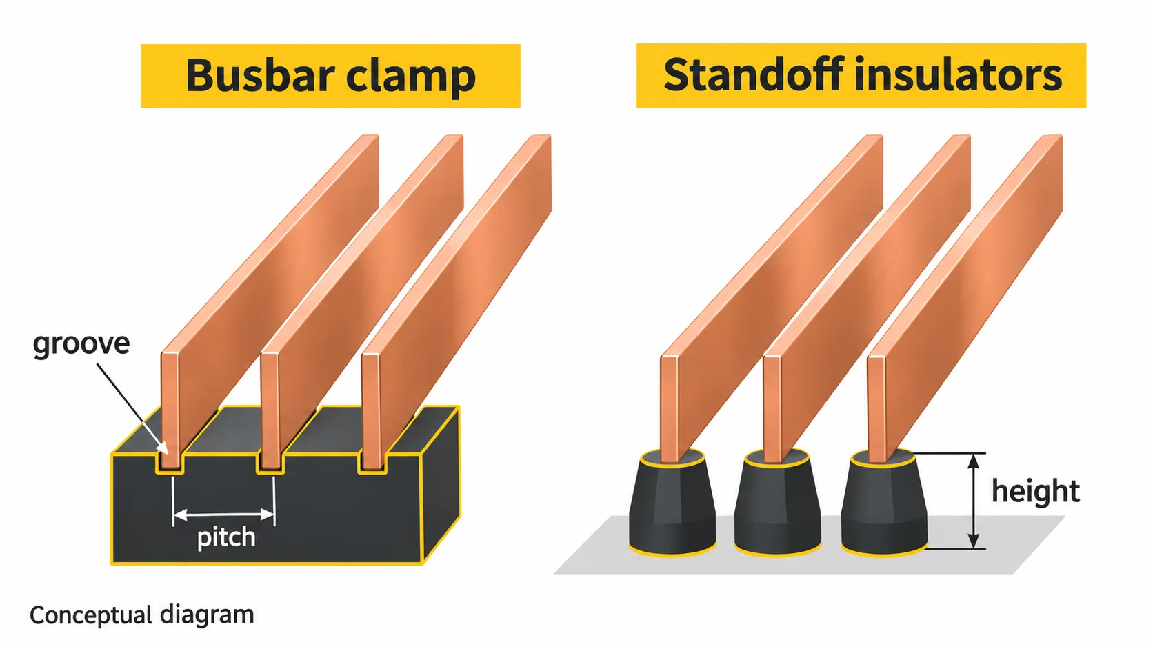
Reading a busbar clamp: groove width against bar thickness
The groove is the seat that positions the bar, so read its width against the thickness of the bar entering that groove. A groove narrower than the bar cannot seat it. A groove far wider than the bar does not position it. This is a fit principle, not a clearance specification: the DL and EL pages publish no clearance or tolerance figures from which to prescribe a fit allowance.
Mark the bar’s orientation on the layout before comparing dimensions. Do not compare a groove-width label with the bar’s broad face simply because both are described as a width on separate drawings. Identify the section entering the groove and match that section to the groove label in the selected clamp view. Keep the complete bar dimensions in the enquiry so the intended orientation is unambiguous.
DL: the prefix identifies groove width within the stated families
The YOCL DL series busbar clamp page lists 18 model designations in six drawing families, with lengths from 155–400 mm. Its listed profile width is 30 mm and height is 35 mm; the illustrated components are red. These are DL product dimensions, not requirements for a busbar layout.
For the D3, D4, S3 and S4 families, the page connects the model prefixes 6, 8, 10 and 12 to groove width A, in millimetres. Thus, 8D3 identifies an 8 mm groove option within that drawing family. The suffix still matters because it takes the buyer to the complete length and mounting arrangement.
The following family values come from the DL page’s dimension table. All dimensions are in millimetres; the groove-width options apply within each listed family.
| DL drawing family | Length | Groove width A options | Groove depth label | Hole centre spacing | Repeated groove spacing |
|---|---|---|---|---|---|
| D3 | 220 | 6, 8, 10, 12 | 10 | 80 | 80 |
| D4 | 300 | 6, 8, 10, 12 | 10 | 160 | 80 |
| S3 | 295 | 6, 8, 10, 12 | 10 | 105 | 105 |
| S4 | 400 | 6, 8, 10, 12 | 10 | 210 | 105 |
Hole centre spacing and repeated groove spacing are separate dimensions. The former locates mounting holes; the latter describes the built-in pitch between repeated groove positions. They happen to share a value in some rows, but the D4 and S4 rows show why they cannot be treated as the same field.
For a parallel group, that repeated groove spacing tells the buyer whether the proposed bar positions match the component. It is catalogue geometry, not a recommended pitch for other assemblies. If the layout’s bar positions do not match, increasing the overall clamp length does not by itself resolve the mismatch.
Keep the compact pair and complete designations distinct
The separate 7D3 and 7D4 models both list 7 mm grooves and 60 mm repeated groove spacing. Their lengths are 155 mm and 215 mm, respectively, while their groove depth labels are 5 mm and 6 mm. Read these as their own drawings rather than extending the other families’ groove-depth entry to them.
YOCL’s DL selection guide calls for the complete model to be selected by length, groove width and mounting hole arrangement. Its ordering guide explicitly says to retain the D or S family suffix. Quote the full designation, not just a groove-width number. The page does not explain the meaning of the letters or suffix numerals; their practical importance is that they distinguish drawings that must not be substituted casually.
Reading the EL range: length names do not replace drawings
The YOCL EL series busbar clamp page lists 13 models, with overall lengths from 100–500 mm. Its model number matches the listed overall length in millimetres: the range is EL-100, EL-125, EL-130, EL-180, EL-210, EL-220, EL-270, EL-270/D, EL-271, EL-295, EL-370, EL-409 and EL-500.
This naming pattern helps locate a candidate length. It does not establish the groove option, end profile or mounting interface. Those fields are model-specific. The EL guide therefore asks buyers to select by overall length, end profile, groove dimensions and mounting features together.
Read groove labels in their own model context
EL-180 uses A for its 7 or 11 mm groove options; EL-210 uses W for its 7 or 11 mm options. A letter is a drawing label in that model’s context. Do not carry a label interpretation from another EL drawing simply because the available values look familiar.
The same discipline applies to hole callouts. Match the callout to the feature and view on the complete drawing, then compare it with the intended mounting layout. A model’s listed length alone cannot settle whether its mounting features suit an existing panel.
EL-270: order a complete A/B pair
The EL page lists the following EL-270 groove options as matched drawing dimensions, all in millimetres:
| A | B |
|---|---|
| 12 | 7 |
| 12 | 0 |
| 11 | 6 |
| 10 | 5 |
Select and quote one complete A/B pair. These are not independent menus from which to combine any A value with any B value. Retain the published 12/0 option exactly when discussing it; the table does not authorize an interpretation of what its zero label means in the assembly. The complete drawing resolves which features the labels describe.
EL-270 and EL-270/D are separate designs
Both models list 270 mm overall length, but EL-270 lists 35 mm end/profile width and 35 mm height. EL-270/D lists 30 mm end/profile width and 40 mm height. Matching the length does not make the designs interchangeable. Keep the full model, including /D, with its own groove and mounting information.
The EL dimension table also leaves EL-210 overall height as “Not specified.” Keep that gap visible. Do not derive a height from a neighbouring model, a photograph or the length-based name. If available height controls the layout, obtain the applicable drawing dimension before accepting EL-210 as a candidate.
The EL page’s embedded photograph and image-based dimension sheet currently depict ribbed insulators rather than the clamp models in its text tables. Use the clamp tables for the listed options, and request the matching EL clamp drawing before ordering. Do not transfer properties from that unrelated image sheet to an EL clamp.
When each fixing logic fits
Start by marking what the arrangement needs to locate: a row of parallel bars, individual fixing points, or both. Then separate the component’s function from the details still needed to specify it.
| Bar-layout requirement | Fixing logic to investigate | Decisive check |
|---|---|---|
| Parallel bars need group positioning across a run | Grooved busbar clamp | Bar thickness, groove pitch, overall length and mounting features must fit the layout |
| A single bar or tap needs support at defined points and height | Standoff insulator | Identify the individual supports and the specified electrical separation |
| A parallel run also needs individual elevated support points | Clamp and standoff arrangement together | Resolve each interface and how the components mate within the layout |
| Bar positions or required component properties remain undefined | Keep the component choice open | Settle those inputs before issuing a model-specific order |
A clamp can position the parallel group at its grooved mounting locations; that does not turn its overall length into the supported length of the whole bar run. Equally, a standoff beneath a bar does not define the groove pitch of a separate positioning component. Name the role of each part on the arrangement drawing so the enquiry preserves both tasks.
YOCL’s EL selection guide explicitly tells buyers to “confirm the required mating clamp or support arrangement for the chosen busbar layout.” That is the basis for considering both logics in one assembly, rather than treating them as mutually exclusive alternatives. It is not a declaration that any clamp will mate with any standoff.
For the separate application task, see busbar supports for battery and combiner bars. If the unresolved interface is on the standoff side, use the insulator dimensions and mounting-drawings guide. Neither task needs to be repeated to decide whether the layout requires group positioning.
What the clamp pages do not declare
Neither the DL nor EL clamp listing declares a material, voltage rating, insulation property or clamping force for these clamp models. Their declared function is supporting and positioning busbars. A red appearance, a shared catalogue category or the word “support” cannot supply the missing properties.
Those absences create specific pre-order questions. Ask YOCL to identify the material for the chosen model and confirm the clamp’s intended electrical duty in the proposed assembly. Where the arrangement requires an electrical-separation function, ask which component supplies it and what model-specific documentation establishes it. Where a retention requirement controls acceptance, request the applicable information for that exact component and arrangement.
Keep those questions attached to the model and layout rather than asking whether “busbar clamps” generally have a particular rating. A nominal groove match only establishes a geometry candidate. It does not answer the undeclared-property questions, and a clamp should never be specified as if its product page declared it to be an insulator.
Ordering checklist: preserve the complete drawing identity
The DL and EL pages’ own guides lead to the following enquiry record. Complete it from the selected drawing and proposed bar layout before requesting a quotation.
- Full model designation: retain the DL family suffix and distinguish EL-270 from EL-270/D.
- Groove width or option: give the DL groove width A or the relevant EL groove option; for EL-270, state the complete paired A/B values.
- Length: confirm the drawing’s overall length alongside its profile and mounting features.
- Busbar dimensions: provide the bar dimensions and show which thickness enters the groove.
- Mounting layout: include the bar arrangement, groove positions and intended mounting interface; identify any mating clamp or support arrangement.
- Quantity: state the required quantity for the specified model and groove option.
Keep the undeclared-property questions from the preceding section with this record. A useful enquiry lets YOCL check a particular component against a particular arrangement. The Busbar Supports & Insulators range provides the catalogue route when that arrangement requires components from both fixing logics.
Buyer questions
Is a busbar clamp an insulator?
Not as YOCL lists these clamp series. The DL and EL pages declare support and positioning, with no insulation rating. Electrical separation is an assembly input to confirm for the chosen component arrangement.
Does the DL model number tell me the groove width?
For D3, D4, S3 and S4 families, the prefix identifies groove width A. The compact 7D3 and 7D4 drawings are separate. Always retain the full designation because the suffix selects the rest of the geometry.
Can an assembly use clamps and standoffs together?
Yes. The EL guide asks buyers to confirm the mating clamp or support arrangement. Identify each component’s role and confirm the actual mating interfaces; the guide does not establish universal compatibility.
What groove width do I need?
One that seats and positions the bar’s thickness in the intended orientation. Compare the actual bar section with the model’s groove drawing, then resolve the fit with YOCL; no published tolerance figures support a universal allowance here.
References
- YOCL ELECTRIC, DL Series Busbar Clamps. YOCL product information: dimension table, drawing-family notes, selection guide and ordering information.
- YOCL ELECTRIC, EL Series Busbar Clamps. YOCL product information: model dimensions, hole and groove labels, paired groove dimensions, selection guide and ordering information.
- YOCL ELECTRIC, What Is a Busbar Insulator?. Standoff function and threaded fixing interfaces.