
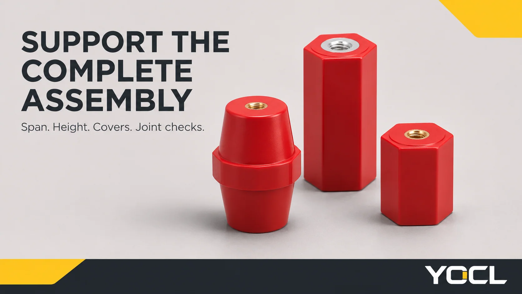
Busbar supports in battery and combiner enclosures must keep the bar aligned, separated from the mounting panel and compatible with its joint covers. Review the supported span, installed standoff height, cover envelope and documented post-installation joint check together. These decisions reduce avoidable mechanical stress and help preserve the intended assembly, but a support is not a cooling device: it cannot correct an underrated bar or a poorly made electrical connection. The loose-stud check is a way to detect a problem before further service, not a guarantee against every hot bar.
Battery circuits can release substantial short-circuit energy, and a combiner can have several sources. This article is for inspection, specification and maintenance planning; hands-on checks belong to qualified persons on equipment that has been de-energized, isolated from all relevant sources and verified safe under its procedure.
Why battery and combiner bars challenge their supports
Battery bars combine substantial conductors, cable lugs and connection hardware in a limited enclosure. The cables may be flexible, but their weight and preferred bending direction can still load the bar. A cable brought onto a stud under strain can pull the joint out of its intended alignment. A support then carries more than the bar’s weight alone.
Current through a resistive joint produces local heat. Changes in load and temperature can also change the mechanical condition of a bolted connection. The fact that a system operates on DC does not remove those joint concerns, although not every installation has the same charging, discharge or temperature cycle. Plan for the actual service pattern rather than assuming a daily cycle applies to every bar.
A reported owner case illustrates the uncertainty. After a combiner busbar suffered heat damage, its replacement used a generic standoff arrangement, and the owner wanted the original covered format back. Replies proposed two different explanations: inadequate bar capability for the actual duty, or a loose connection creating a local hot spot. The cause remained unresolved. Restoring a cover or changing the supports would not, by itself, decide between those possibilities.
That distinction should control an inspection. Damage concentrated near a stud makes the connection worth investigating; it does not prove that the stud was loose or establish the bar’s usable current rating. Discoloration spread elsewhere also needs assessment in context. Do not diagnose an entire assembly from the appearance of one damaged component.
Separate the mechanical function from the electrical connection. The support maintains position and separation; the lug-to-bar interface carries current through its specified contact arrangement. A support mounting fastener and an electrical joint fastener may be close together but perform different jobs. The busbar insulator overview explains that component boundary without turning every support into an electrical terminal.
Support spacing: define the span, then request its basis
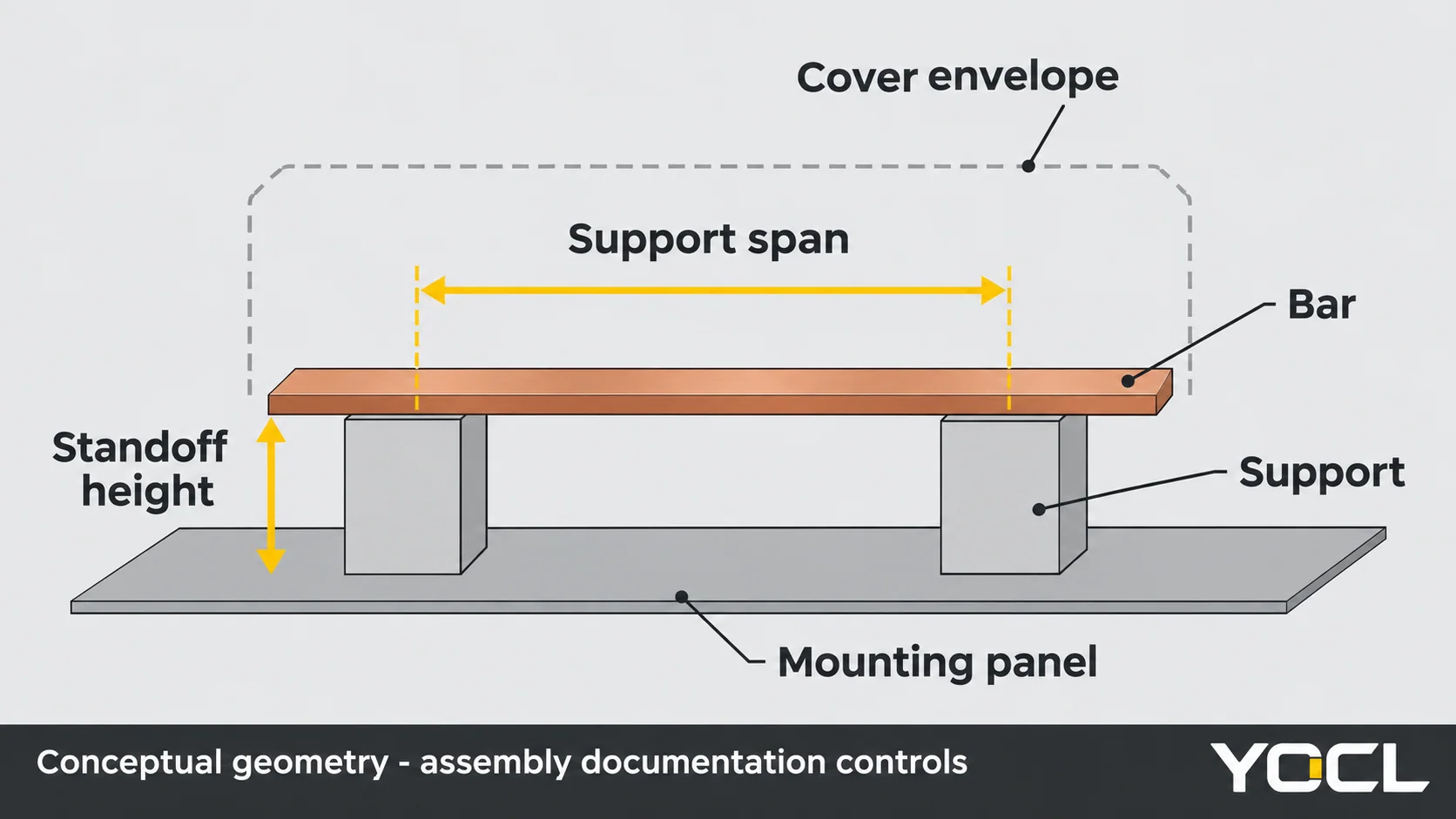
The span between supports affects how the bar behaves as a mechanical member. Weight, bar orientation, cable forces and the constraints at its fixings all matter. A layout that holds a bare bar straight before cabling may behave differently once the lugs, cables and cover have been added.
Start with the installed arrangement drawing. Identify which locations actually support the bar and which merely locate a cover or restrain a cable. Record where cables approach and whether their weight is supported independently. Do not count a cover clip as a structural bar support unless the assembly documentation gives it that function.
Copper for Busbars, issued by the Copper Development Association and European Copper Institute, discusses section orientation, span, restraint and the forces acting on supports. Adjacent current paths can attract or repel according to their arrangement and current direction. Fault forces are therefore an assembly-design input, not a reason to choose a span by eye. This article does not transfer that guide’s AC examples or calculations into a battery design.
The useful request to the assembly designer is specific: what documented arrangement establishes the support positions for this bar and its connected cables? Provide the bar dimensions and weight, enclosure layout, attachment conditions and applicable fault-duty information. A component strength field does not answer how an installed bar shares load between supports or what happens at its connections.
Do not improvise a closer span as a universal cure either. Moving supports can change fixing constraints, cable alignment or access under the cover. A revised arrangement needs review against the complete assembly, even if it looks more rigid. Likewise, replacing a support with a taller body changes the geometry rather than simply adding clearance.
For busbar supports in a battery enclosure, pay particular attention to heavy cable approaches and service access. For busbar supports in a combiner enclosure, review the assembled bar, all connected conductor routes and the cover together. Neither application supplies a generic spacing distance. The decision remains tied to the documented mechanical arrangement.
Standoff height: check the installed envelope
Height determines where the supported bar sits relative to the mounting panel. The space above and beside it must accommodate lug barrels, hardware, the permitted cable bend and the cover. These are installed relationships; an overall support height alone is not the complete clearance drawing.
Consider the whole stack: mounting surface, support body, bar position, connection hardware and cover interior. Depending on the arrangement, the published body height may not equal the distance from the panel to the highest conductive part. Projecting fasteners, lug orientation and the cover’s attachment method can change the final envelope. Do not solve a cover collision by forcing a cable bend or removing protective material.
The relevant YOCL series illustrate how to request candidate geometry:
| Published series context | What its model information provides | What still belongs to the assembly |
|---|---|---|
| SM busbar support insulators | BMC or SMC glass-fibre-reinforced unsaturated polyester body, metal inserts; 12 models, SM-20 to SM-100, with heights of 20–100 mm | Actual support positions, installed stack and approved fastening arrangement |
| EN hexagonal standoff insulators | BMC/SMC body; 7 models with heights of 25–120 mm; thread configurations have their own diameter, depth and torque-strength entries | Complete joint hardware, cover fit and installation tightening instructions |
These are catalogue geometry ranges, not recommended battery-bar heights. Choose the exact model row that corresponds to the reviewed arrangement. Keep its thread configuration attached to that model; similar-looking supports can leave different engagement and mounting questions unresolved.
Electrical-duty screening remains a separate task. Use the busbar support insulator selection guide for that assessment rather than treating extra height as proof of suitable insulation duty. For the manufacturer’s dimension labels and thread records, use the dimensions and mounting-drawings guide. Here the task is fitting the selected support into its actual application, not repeating either guide’s selection method.
Before accepting the mechanical layout, require the drawing to show the cable approach with the cover fitted. A bar can clear the back panel while its lug barrel presses against a shroud. Resolving that conflict before installation is more useful than discovering that the cover cannot be refitted after the connections are made.
Covers: protect the interface without hiding its condition
A correctly specified cover or shroud restricts accidental contact with the conductive bar and connection hardware. In a battery enclosure, it can also reduce the opportunity for a dropped tool or loose metal item to bridge conductive parts. That function depends on the complete shape, attachment and cable openings; simply placing plastic over a bar does not establish the protection provided.
Include cover access in the layout review. Can the specified cover be fitted and removed under the maintenance procedure without forcing the cables or disturbing a joint? Are its attachments independent of the electrical contact stack, or does the assembly use a documented combined arrangement? Does the intended access remain possible after all cables are installed? These are questions for the actual cover and assembly documents.
A cover is not a replacement for spacing, insulation coordination or a sound connection. It also does not make work on exposed parts safe when it has been removed. HSE’s safe-working guidance addresses isolation and protection from adjacent live parts in its UK scope; local equipment procedures still determine the work arrangement.
Warping, heat-darkened areas or damage concentrated near a connection deserve investigation of the joint beneath the cover. Replacing the cover alone leaves the possible source untouched. Conversely, cover damage does not establish that a support failed: an inadequate bar, a contact problem or another local condition may be involved.
Keep inspection access and acceptance evidence in the plan. Covers can hide the surfaces a maintainer wants to examine, and an undamaged exterior does not prove that a hidden connection is sound. Specify how the equipment’s maintenance process addresses covered joints rather than making an improvised opening or omitting the cover for convenience.
The cited YOCL support pages do not establish the availability, fit or protective performance of a particular battery-bar cover. Request the appropriate cover from the responsible assembly supplier. Do not assume a generic support and a visually similar shroud form a documented interchangeable system.
The loose-stud check: review the joint, not just the nut
Include the first documented post-installation review in the commissioning and maintenance plan. If the equipment instructions call for a check after initial operation or thermal cycling, record when it is due and what method they specify. There is no universal elapsed time or instruction to re-tighten every busbar connection after service.
The distinction matters. EPRI’s Reliability and Maintenance of Bolted Busbar Connections describes differing industry practices and uncertainty around blanket retorquing. Its inspection discussion considers connection condition, corrosion, heat damage and appropriate checks. The report concerns power-station buswork; it supports a cautious maintenance principle, not a battery-terminal torque schedule.
For a fine-stranded cable, establish the approved conductor-and-lug combination and its termination instructions. Bedding or relaxation within a connection can matter, but a properly specified crimp lug must not be assumed to need repeated tightening merely because the cable is flexible. Review the lug termination, its contact with the bar and the bolted stack as separate interfaces. A loose stud and a poorly made crimp require different corrective work.
The maintenance record should distinguish observations from conclusions:
| Observation | What it should trigger |
|---|---|
| Darkened insulation or a discoloured cover near a stud | Assess the nearby connection and its service conditions; do not declare the cause from the mark alone |
| Distorted cover or damaged support | Hold the affected arrangement for assessment, including the joint and maintained separation |
| Oxidised, discoloured or softened-looking lug surface | Examine the component and contact condition under the approved maintenance process |
| Persistent unusual smell or a reported hot joint | Treat as a reason for competent assessment, not an acceptable condition to monitor casually |
| Movement, misalignment or cable strain | Establish which fastening or support interface has changed before deciding the repair |
Appearance cannot confirm that a lug has annealed, quantify connection resistance or establish whether the bar is underrated. Those questions need the responsible assessment and any required tests. A witness mark also records relative position, not the actual retained contact pressure.
Do not use torque strength as the tightening instruction
The SM and EN pages explicitly distinguish their listed torque strength from recommended installation tightening torque. A strength field for a support insert is not a setting for a lug nut, and a lug-nut setting does not automatically apply to the support mounting screw. Thread size alone is not enough to transfer an instruction between those interfaces.
Obtain the assembly’s exact joint and mounting instructions, including the specified hardware arrangement. A fastener can feel tight while the intended contact stack is wrong or the insert is damaged. Repeatedly applying more torque does not resolve missing engagement information or restore a heat-damaged component.
Where damage or an unsound connection is confirmed, the qualified repair plan should remake the joint with sound, specified parts and replace affected heat-damaged supports or covers as required. Use the cracked-insulator inspection and replacement guide for support-condition decisions. The replacement must restore the documented alignment, spacing and cover fit, not merely remove the visible symptom.
Specification checklist for a battery or combiner bar
Request a package that can be reviewed as an arrangement, rather than ordering a support by height alone:
| Document or input | Decision it needs to resolve |
|---|---|
| Assembly layout and support-position basis | Supported span, bar orientation, restraints and mounting surface |
| Bar and cable arrangement | Weight, cable approach, lug position and independently managed cable loads |
| Exact support model and configuration | Body geometry, insert details and matching model-table information |
| Joint and mounting hardware instructions | Separate installation requirements for the electrical joint and support attachment |
| Cover drawing and availability | Full installed envelope, attachment, access and replacement compatibility |
| Commissioning and maintenance requirements | Initial acceptance, any specified post-operation review and release criteria |
Use the busbar supports and insulators category to identify the candidate series requiring documentation. A category listing does not establish that its parts are approved for a specific battery or combiner assembly. State the application and provide its drawing so the enquiry can address the actual interfaces.
Keep changes controlled after selection. Replacing an insulating body, changing a support position, substituting joint hardware or adopting another cover can alter more than one relationship. Record what changed and obtain the required review before treating the original arrangement evidence as still applicable.
The final acceptance should connect the physical arrangement to its documents: the bar is supported as specified, the cables do not force it out of alignment, the protective parts fit, and the joints have passed the required checks. That closes the mechanical-support task without pretending to complete the separate electrical design of the battery system or combiner.
FAQ
Can I choose busbar support spacing from the enclosure size?
No. Enclosure size is one layout input. The bar, restraint conditions, cable loads and applicable fault-duty assessment determine the required arrangement. Request the documented support positions rather than assuming that any span fitting inside the box is acceptable.
Does a taller standoff automatically make the assembly safer?
No. Height changes the installed bar and joint position. It can affect cable bends, cover fit and the overall arrangement. Use the exact model geometry within the reviewed design; extra height does not establish electrical suitability or replace mechanical verification.
Should every busbar stud be retorqued after the first heat cycle?
No universal retorque instruction applies. Follow the exact equipment’s commissioning and maintenance requirements. Distinguish a permitted verification from automatic further tightening, and never use a support’s torque-strength figure as a lug-joint setting.
Is replacing a melted cover enough to return a bar to service?
No. Heat damage calls for assessment of the underlying joint, components and service conditions. A loose connection and inadequate bar capability remain different possibilities until investigated. Restore the specified connection and protective arrangement before the required release checks.
References
- Copper Development Association / European Copper Institute, Copper for Busbars: Guidance for Design and Installation, revised May 2014, mechanical arrangement and short-circuit forces.
- YOCL product information, SM Series Busbar Support Insulators and EN Hexagonal Standoff Insulators, model geometry and limits of torque-strength fields.
- HSE, Electricity at Work: Safe Working Practices, scoped isolation and adjacent-part precautions.
- EPRI, Reliability and Maintenance of Bolted Busbar Connections, inspection principles and limits of blanket retorquing; power-station buswork scope.