
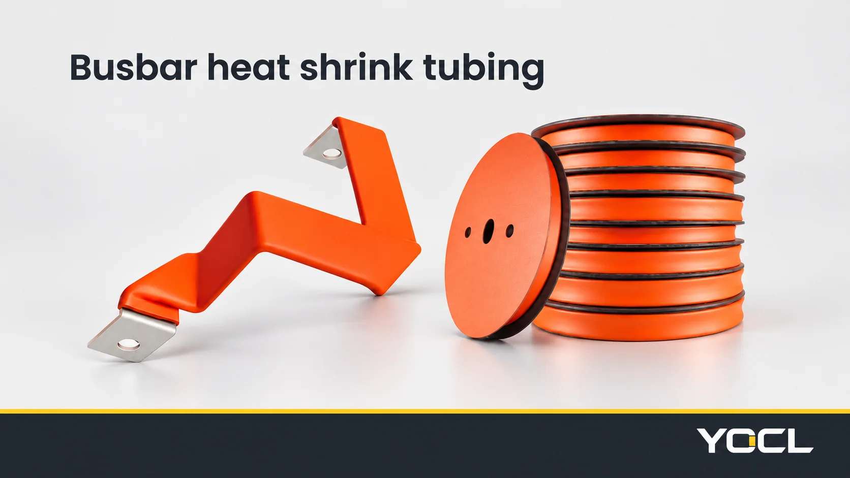
To size busbar heat shrink tubing, convert the flat bar’s perimeter to an equivalent diameter, allow clearance for sliding the tube on, then check the tubing table’s application range, supplied internal diameter, maximum recovered internal diameter and recovered wall thickness. The bar’s width alone does not determine the tube size. For YOCL HSNE-F, overlapping ranges and dimensional tolerances make those checks essential before confirming a size on the actual bar.
This method identifies a dimensional candidate for a flat bar. A calculated match does not, by itself, establish installation clearance or the insulation performance of the finished assembly. The examples below show both a close clearance boundary and a choice between two overlapping HSNE-F rows.
Why matching the tube diameter to bar width is unreliable
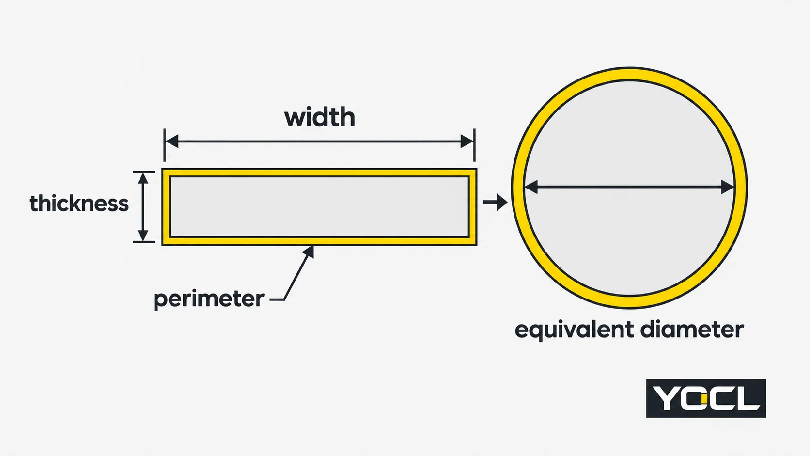
A rectangular bar has two wide faces and two narrow edges. The sleeve must surround that complete boundary; measuring only one face leaves out the thickness and confuses a straight distance with a perimeter-based diameter.
However, buying a tube whose stated diameter equals the bar width does not always make it too small. For a thin flat bar, the equivalent diameter can be substantially smaller than the width. DOWE’s flat-product sizing FAQ illustrates this with a 20 mm-wide, 1 mm-thick strip: its perimeter is 42 mm and its equivalent diameter is about 13.4 mm. That example demonstrates why width matching is not a valid selection rule; it does not support a universal undersizing claim.
Depending on thickness, supplied dimensions and installation allowance, a width-based guess can leave excess material or insufficient clearance. A tube that cannot slide over the actual component is unsuitable even if its nominal name looks close. At the other extreme, an unnecessarily large tube may have a recovered bore that remains too large to grip, or leave an unsatisfactory recovered cover. The dimensions must support both starting and finishing conditions.
Use the general heat shrink tubing size chart for round-cable diameter selection. The additional task here is translating a flat cross-section into the diameter used for the HSNE-F table check.
Convert the four-sided perimeter into an equivalent diameter
HellermannTyton’s Australian catalogue describes the busbar method in “How to choose the correct sized Heatshrink”: total all four sides, divide by π, and add 10% for installation clearance. Its worked 50 × 10 mm example then selects from its own product range. The method is useful here; its product selection is not an HSNE-F recommendation. See catalogue page 112.
For the conversion itself:
Equivalent diameter = perimeter ÷ π.
Measure the bar width and thickness in millimetres, then add the lengths of its four sides. π relates a circle’s circumference to its diameter, so this calculation describes a circle with the same boundary length as the rectangular cross-section. It does not turn the bar into a circular object or predict every detail of how the polymer moves around its corners.
Keep two results separate. The equivalent diameter describes the bare cross-section for comparison with the application range and recovered diameter. The clearance allowance concerns getting the supplied tube onto that cross-section. Do not use the larger, clearance-adjusted figure as though it were the bar’s own size.
The 10% allowance is the cited catalogue method, not a separate HSNE-F tolerance guarantee. Retain calculation precision until checking the actual row. Small rounding differences matter when the calculated starting requirement is almost equal to the listed supplied diameter.
Read the HSNE-F busbar heat shrink tubing table as four checks
The YOCL HSNE-F product page instructs buyers to use the application range together with supplied I.D., maximum recovered I.D. and recovered wall thickness, and to check fit over the actual busbar or component before choosing. I.D. means internal diameter.
Read each candidate row this way:
- Application range: the bar’s converted equivalent diameter must lie within the published interval. This screens candidates; it does not finish the selection.
- Supplied I.D.: the unheated tubing must slide over the actual bar and the features along its insertion path, with the required clearance and dimensional tolerances considered.
- Maximum recovered I.D.: this limit must be below the bar’s equivalent diameter so that the tube has recovery available to grip it. It is not the final installed bore around the rectangle.
- Recovered wall: record the published wall thickness and its tolerance for the selected row. Do not treat that table value as a measurement of every point on an installed rectangular cover.
HSNE-F dimension and application-range table
All dimensions below are in mm. The five columns reproduce YOCL’s published nominal values and limits; the product page additionally lists supplied-I.D. and wall tolerances. Those tolerances still apply when evaluating a close fit. Packing lengths appear in the ordering section.
| Nominal size | Supplied I.D. | Max. I.D. after recovery | Wall after recovery | Application range |
|---|---|---|---|---|
| 10/5 | 10.5 | ≤5.00 | 0.56 | 5.3–10.1 |
| 11/5.5 | 11.5 | ≤5.50 | 0.56 | 5.8–11.1 |
| 12/6 | 12.5 | ≤6.00 | 0.56 | 6.3–12.1 |
| 13/6.5 | 13.5 | ≤6.50 | 0.70 | 6.8–13.1 |
| 14/7 | 14.5 | ≤7.00 | 0.70 | 7.3–14.1 |
| 15/7.5 | 15.5 | ≤7.50 | 0.70 | 7.8–15.1 |
| 16/8 | 16.5 | ≤8.00 | 0.70 | 8.3–16.1 |
| 17/8.5 | 17.5 | ≤8.50 | 0.70 | 8.8–17.1 |
| 18/9 | 19.0 | ≤9.00 | 0.70 | 9.3–18.1 |
| 20/10 | 22.0 | ≤10.00 | 0.80 | 10.5–21.0 |
| 22/11 | 24.0 | ≤11.00 | 0.80 | 11.5–23.0 |
| 25/12.5 | 26.0 | ≤12.50 | 0.90 | 13.0–25.0 |
| 28/14 | 29.0 | ≤14.00 | 0.90 | 14.5–27.0 |
| 30/15 | 31.5 | ≤15.00 | 1.00 | 17.0–29.0 |
| 35/17.5 | 36.5 | ≤17.50 | 1.00 | 20.0–30.0 |
| 40/20 | 41.5 | ≤20.00 | 1.00 | 22.0–35.0 |
| 45/22.5 | 46.5 | ≤22.50 | 1.00 | 30–45 |
| 50/25 | ≥50 | ≤25.00 | 1.10 | 28–45 |
The intervals overlap and do not form a continuous nominal-size scale. In particular, 45/22.5 lists 30–45, while 50/25 lists 28–45. Keep those intervals as published rather than adjusting them into a smoother progression. The ≥50 entry for 50/25 is a minimum supplied I.D.; it is not a symmetric tolerance.
Example 1: a 12 × 3 mm bar and the 10/5 clearance boundary
For this illustrative bar, adding 12 + 3 + 12 + 3 gives a 30 mm perimeter. Dividing 30 by π gives approximately 9.5493 mm, usually displayed as 9.5 mm.
The 10/5 row’s 5.3–10.1 mm application range contains that equivalent diameter. Its maximum recovered I.D. is ≤5.00 mm, below the bar’s equivalent diameter, and its listed recovered wall is 0.56 mm. These fields make 10/5 a dimensional candidate.
The supplied-diameter check needs more care. Adding the catalogue method’s 10% clearance to the unrounded equivalent diameter gives approximately 10.5042 mm. The row lists 10.5 ± 0.30 mm supplied I.D. Its central value is essentially on the rounding boundary, and the lower tolerance limit is 10.2 mm. Rounding the bare equivalent diameter down to 9.5 mm before adding clearance would hide this issue.
Therefore, do not describe 10/5 as guaranteed to slide onto every 12 × 3 mm bar with that allowance. Confirm actual bar dimensions, available bore and insertion fit. If the clearance check fails, compare 11/5.5: its range is 5.8–11.1 mm, supplied I.D. 11.5 ± 0.30 mm, maximum recovered I.D. ≤5.50 mm, and recovered wall 0.56 mm. It offers more starting room on paper, with physical fit still to be checked.
Example 2: a 25 × 5 mm bar and overlapping candidates
Adding 25 + 5 + 25 + 5 gives a 60 mm perimeter. Dividing 60 by π gives approximately 19.0986 mm, or 19.1 mm. Adding 10% gives approximately 21.0085 mm for the starting-clearance comparison.
Compare these two candidate rows:
| Check | HSNE-F 20/10 | HSNE-F 22/11 |
|---|---|---|
| Application range | 10.5–21.0 mm; includes 19.1 mm | 11.5–23.0 mm; includes 19.1 mm |
| Supplied I.D. | 22.0 ± 0.50 mm | 24.0 ± 0.50 mm |
| Max. recovered I.D. | ≤10.00 mm; below 19.1 mm | ≤11.00 mm; below 19.1 mm |
| Recovered wall | 0.80 ± 0.15 mm | 0.80 ± 0.15 mm |
Both pass these dimensional comparisons on paper, including the 10% starting allowance even at their lower supplied-I.D. tolerance limits. The 20/10 candidate begins closer to the required size and has less excess circumference to recover than 22/11. That is a comparison of these fields, not a universal instruction to choose the smallest nominal row.
They are not the only rows whose application ranges contain 19.1 mm: 25/12.5, 28/14 and 30/15 also do. A range match alone therefore cannot identify one mandatory size. Use the remaining fields and confirm fit over the actual bar before committing to an order.
What HSNE-F covers, and where its specifications stop
YOCL identifies HSNE-F as flame-retardant single-wall, radiation cross-linked polyolefin tubing with a 2:1 shrink ratio. Its stated applications include electric and hybrid vehicle battery systems, copper and laminated busbars, battery electrical connections, conductive components and connection covering. The page also lists solder-joint protection against corrosion; this does not establish an environmental seal.
Standard orange supports visual identification in vehicle electrical systems, and custom colours are available. Colour does not replace a size or application check. For an introduction to the construction terms, see what heat shrink tubing is; broader ratio selection belongs in the 2:1, 3:1 and 4:1 comparison.
HSNE-F provides insulation and surface covering without an adhesive lining or environmental seal; use the single-wall versus dual-wall guide when a sealed joint is required. Mechanical support is a separate layer addressed in busbar supports for battery and combiner bars.
This is a low-voltage/new-energy-vehicle busbar product, not medium-voltage switchgear tubing selected by voltage class. The page lists VW-1 flame retardancy with ASTM D2671 as the test method. Its ≥15 kV/mm breakdown strength under ASTM D149 is material test data. The 2500 V for one minute, no breakdown entry under the 600 V withstand-voltage heading is listed with UL 224. Neither entry establishes an insulated-bar assembly rating. Insulation coordination of the finished assembly remains the assembler’s design duty.
Fit the selected tubing before closing the bar run
YOCL’s installation sequence is short: measure the component, select from the application range and dimensional table, cut the tubing to length and slide it into position. Apply controlled heat evenly until recovery is uniform, remove the heat source, allow cooling, then inspect for complete and uniform coverage.
Because the tube slides on, plan to position it before connections close off the insertion path. It is not a wrap-on repair for a bar that is already enclosed by its connections. A satisfactory straight-section calculation does not make an obstructed insertion route usable.
HSNE-F lists axial change of −5% to +5% under ASTM D2671; use the splice application guide for the general cut-length method and heating-control explanation.
For this series, initial shrink temperature is ≥85 °C, full shrink temperature is ≥125 °C, and the operating range is −55 °C to +125 °C. A product shrink temperature is not a heat-gun dial setting. Keep the applied heating controlled and even as the HSNE-F instructions specify, rather than treating a threshold as a complete heating procedure.
Specify the size and packing in the order
Once fit has been checked, specify HSNE-F, selected nominal size, required colour and quantity. Keep the nominal size paired with its actual table row in the purchase record so that a supplied-I.D. value is not mistaken for the ordering name.
Standard packing is 100 m for 10/5 through 22/11, 50 m for 25/12.5 through 40/20, and 25 m for 45/22.5 and 50/25. State the required quantity clearly alongside the packing length. Where the candidate is near a clearance boundary, settle the actual fit before committing to production quantities.
Sizing questions
Can I just match tube size to busbar width?
No. Use the complete perimeter to obtain the equivalent diameter, then read the product’s dimensional fields. Width matching can mis-size the tube in either direction; it is not a reliable shortcut.
Two sizes’ ranges contain my bar. Which should I choose?
Compare supplied and recovered I.D., tolerances and recovered wall. Confirm that the tube slides onto the actual component and can recover onto it. The 25 × 5 mm example shows why one range match cannot finish that decision.
Is this the same as switchgear busbar tubing rated in kV classes?
No. HSNE-F is specified for new-energy-vehicle busbars and connections. Its product-page test entries do not make it a medium-voltage-class product.
Does orange mean it is only for one polarity?
The page describes orange as the standard identification colour for vehicle electrical systems and offers custom colours. It does not assign a polarity code to HSNE-F.
References
- DOWE, A Guide to Choosing Heat Shrink Tube Specifications and Selecting the Appropriate Inner Diameter, flat-product sizing section.
- HellermannTyton, Australian product catalogue, Insulation, issue November 2025, printed page 112, “How to choose the correct sized Heatshrink.”
- YOCL Electric, HSNE-F 2:1 Flame-Retardant EV Busbar Heat Shrink Tubing, first-party product information: dimensions, selection, test entries, installation and ordering.