
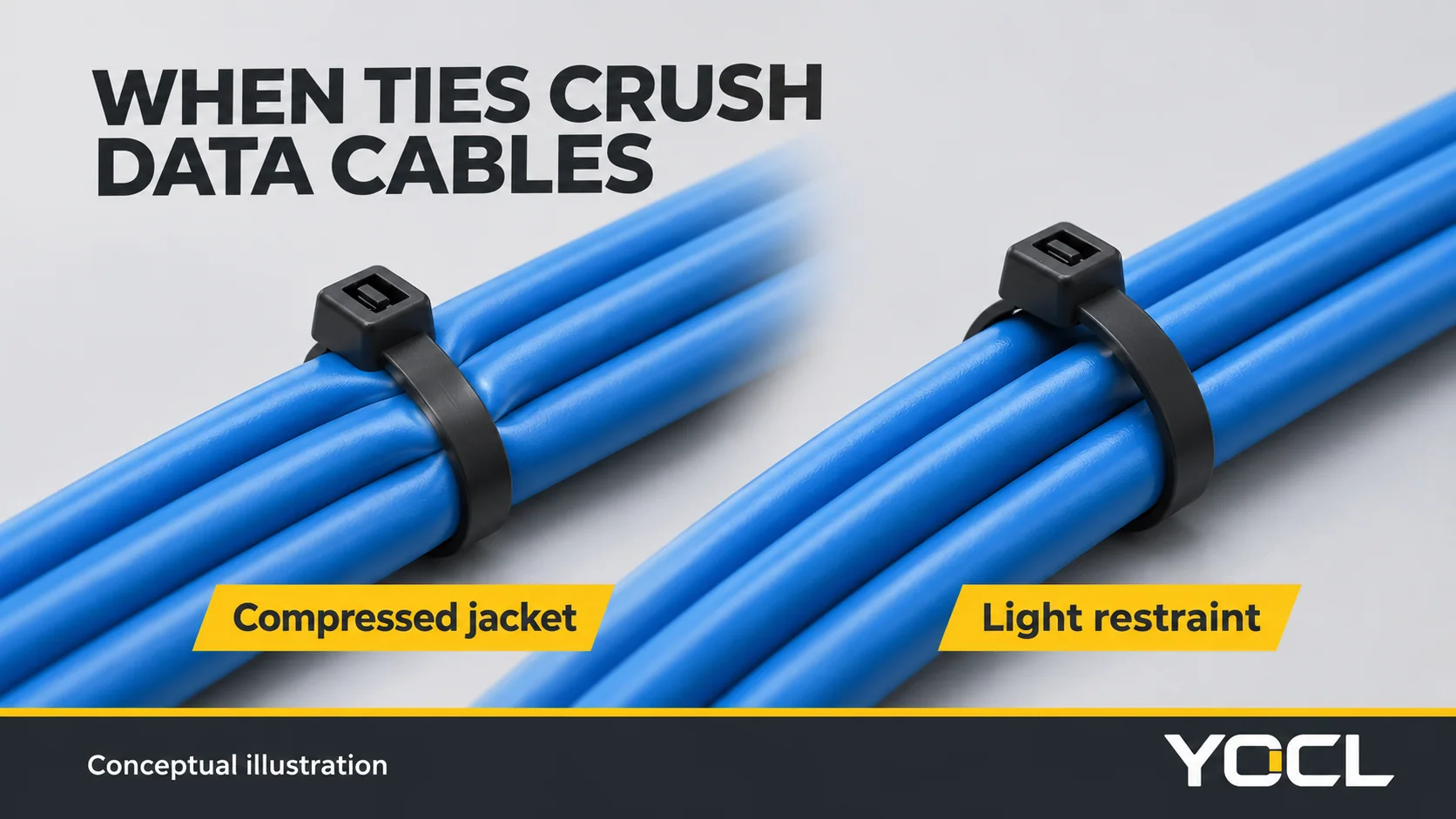
A bundle can look tidy while the cables inside it are under damaging pressure. In a rack, control cabinet or home network, pulling a nylon tie until every cable stops moving can flatten a jacket and disturb the geometry beneath it. The complaint is specific: the fastener used to organize the wiring has become a possible cause of transmission problems.
Short Answer: Yes, zip ties can damage Ethernet cables if tightened enough to crush the jacket and distort the twisted pairs. Optical cables can suffer pressure-induced bending loss or fiber damage. Use light restraint where the cable instructions permit it, and prefer hook-and-loop straps for accessible data bundles. A visible dent is a reason to investigate; a link light or successful speed test does not establish cable certification. Check suspected damage with the appropriate copper or optical tests.
The complaint first: “don’t ratchet them down”
In the HardForum thread CAT6 Cable Clips, a contributor using the name hawk82 warns, “don’t ratchet them down, crushing the cable” and describes how “people whale on them” when tightening. Another contributor, Shadowspawn, favors reusable straps and says, “you can’t crank them down and damage the wire” as with zip ties.
These are individual forum comments, not controlled measurements or verified accounts of either contributor’s professional qualifications. They capture the practical problem: a ratcheting fastener makes it easy to apply more restraint than the cable needs. The second comment should not be read as a guarantee that any hook-and-loop installation is harmless. Cable routing, support and freedom from compression still matter.
The useful distinction is between holding a bundle in position and squeezing it into a rigid shape. A tie can remain intact while the cable it surrounds is damaged. Likewise, a cable can continue carrying traffic while falling short of the transmission performance required for project acceptance.
The measurable damage: what certification can reveal
A continuity pass does not clear a crushed cable
Copper cable certification measures transmission performance against the selected cabling limits. Simply checking that conductors connect to the correct pins does not establish that the installed link still has acceptable high-frequency behavior.
Return loss is one relevant measurement. It describes reflections associated with impedance mismatches along a link. A local change in cable construction can create a reflection even though no conductor is broken. Fluke Networks explains this distinction in its return-loss measurement guidance. A lower return-loss result generally means more reflection; compare the measurement with its applicable limit and margin rather than treating any displayed dB value as an automatic failure.
Near-end crosstalk, or NEXT, concerns unwanted coupling between pairs measured at the transmitting end. Compression can disturb the geometry that helps control that coupling. FOA’s UTP installation tutorial, page 10, explicitly warns that over-tight ties can crush cables enough to cause crosstalk failure. This establishes a credible failure mechanism, not a prediction that every tied bundle will fail.
Find the location before assigning the cause
A certification result identifies a performance problem; it does not automatically identify a zip tie as the cause. A damaged termination, kink or other cable defect can also produce poor results.
Fluke’s HDTDR diagnostic explanation describes how a high-definition time-domain reflectometry trace helps locate impedance discontinuities associated with return-loss problems. Diagnostic distance information can be compared with physical restraint locations. If an event coincides with a tight tie, that correspondence makes the restraint worth inspecting. It is evidence to investigate, not proof by itself. Small discontinuities may also be difficult to resolve individually.
For a useful before-and-after comparison, preserve the original report and photographs, correct the suspect restraint without changing unrelated parts of the link, and repeat the same appropriate test. Record the cable identity, test configuration, affected pairs, limits, margins and physical location. Improvement supports a restraint-related explanation; it does not establish a universal damage threshold.
| Observation | What it may mean | Check that helps distinguish the cause | Appropriate response |
|---|---|---|---|
| Jacket dent at a tie; link still operates | Local compression is present, but transmission impact is unknown | Inspect the cable and run the required certification test | Correct the restraint and retain the test record |
| Return-loss problem with a diagnostic event near a tie | A local impedance change may be involved | Compare diagnostic distance with the actual route and other defects | Inspect that location before changing terminations |
| NEXT failure | Pair geometry or termination workmanship may be involved | Review pair results and diagnostics; inspect both restraint and termination areas | Correct the identified defect and retest |
| Optical loss associated with a compressed section | Pressure-induced bending is possible | Inspect routing and perform the specified optical loss test | Remove the prohibited restraint and assess the cable |
| Poor performance remains after release | Damage may be permanent, or the original cause may be elsewhere | Continue diagnosis using the same acceptance requirements | Repair or replace as the cable system permits |
A relevant published example is Fluke’s cable-damage return-loss case. Its diagnostic trace indicated damaged cable, and its conclusion was replacement rather than repeated retermination. The source does not establish cable ties as the cause. Its value here is the distinction between locating damaged cable and assuming that every failed link needs new connector work.
A marginal pass also needs careful wording: it is not interchangeable with a failed certification result. Keep the tester’s actual verdict and the project acceptance requirements visible. Do not relabel a thin margin as a failure to make a damage claim sound stronger.
How the damage works
Copper: compression changes the transmission geometry
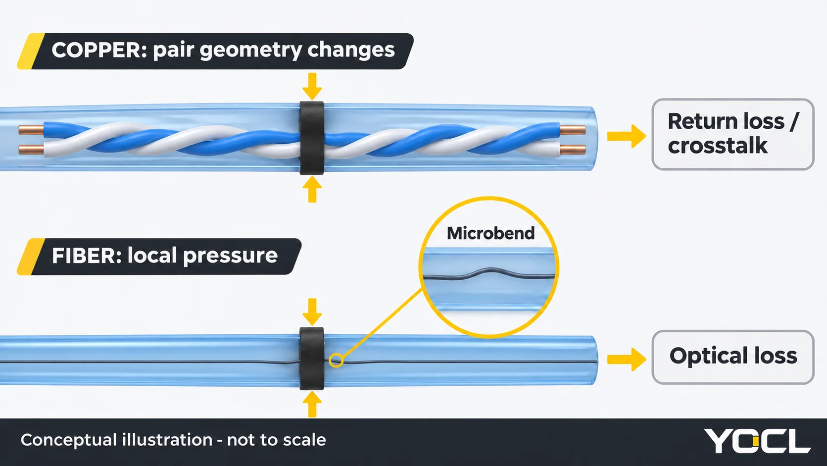
Cat5e, Cat6 and Cat6A cables rely on controlled pair construction. External pressure matters when it changes that construction. A narrow tie pulled hard against a jacket concentrates restraint at a small contact region. The jacket can flatten, and the conductors and pairs beneath it can be displaced.
FOA’s UTP installation guidance connects crushing with changes in twist and pair alignment that affect high-frequency performance. This is more precise than saying a tie necessarily changes the twist pitch throughout the cable. The disturbance can be local, and the cable construction affects how external force reaches the pairs.
That local geometry change can alter impedance and increase reflections, degrading return-loss performance. Disturbed pair relationships can also worsen crosstalk performance. These are related consequences of mechanical deformation, not a mandatory sequence in which NEXT must fail before return loss does. One parameter can be affected more than another.
Pressure can also impair cable balance. Fluke’s Industrial Ethernet CableAnalyzer documentation identifies excessively tight cable ties among factors associated with poor balance and susceptibility to interference. This is another reason a basic connectivity check is an incomplete assessment of cable condition.
Tightness and position are separate variables. Tightness determines whether a particular contact compresses the cable. Multiple tight contacts create multiple suspect locations along the route. Their positions may correspond to diagnostic events, but regular spacing alone is not proof of damage. Spreading out ties will not make an individual crushing contact acceptable; nor should support be removed so widely that the cables sag or load their connectors.
Fiber: local pressure can become optical loss
Fiber optic cable has a different failure mechanism. External compression can impose small deformations on the glass through the surrounding cable elements. Microbending refers to microscopic deviations along the fiber axis, distinct from a visible routing bend. Both can increase attenuation. See FOA’s explanation of macro- and microbending.
The consequence is optical loss, measured in decibels, rather than copper-pair NEXT. Severe mechanical abuse can also break fibers. A clean-looking outer jacket does not establish that the glass is unharmed. Conversely, an optical loss problem does not prove that a tie caused it; connectors and other parts of the optical path also need assessment.
Product instructions can be stricter than general bundling advice. In the CABLExpress Skinny-Trunk installation guide, the manufacturer permits zip ties at its trunks’ protected furcation points, where a metal sleeve protects the fiber. It then states, “For all other applications use ONLY Velcro.”
That is a specific assembly instruction. A furcation is the transition where a trunk separates into individual legs; an ordinary jacket location is not an equivalent attachment point. The protected-point permission must not be transferred to a different trunk, a bare breakout leg or an unrelated patch cord.
Oracle’s Recovery Appliance InfiniBand precautions are direct: “Do not use zip ties to bundle or support InfiniBand cables.” They specify hook-and-loop straps instead. Follow that prohibition for the covered system; a low tension setting does not override it.
How to bundle data cables without damaging them
Restrain the route without compressing the jacket
Use the cable manufacturer’s instructions to decide whether plastic ties are permitted at all. Where they are allowed, close them only enough to keep the bundle organized without deforming the jackets. Fluke’s cable ties and wraps guidance calls for finger-tight restraint and illustrates the difference between deformed and undeformed cables.
Hook-and-loop straps are a practical default for accessible data bundles because they can be opened for additions without cutting beside the cables. They still need suitable support and routing. Avoid using any strap to force a bundle through an awkward bend or to transfer suspended cable weight onto a connector.
| Situation | Practice that protects the cable | Avoid |
|---|---|---|
| Accessible copper patch-cable bundle | Prefer a loosely closed hook-and-loop strap | Pulling the bundle into a rigid, flattened block |
| Copper cable where plastic ties are permitted | Use light hand restraint and inspect every contact | Ratcheting until the cables cannot move |
| Fiber patch cords or exposed breakout legs | Follow the exact assembly instructions; prefer soft restraint | Applying a plastic tie directly because the jacket looks robust |
| A trunk with a documented protected furcation point | Use only the specified attachment location and method | Assuming every furcation contains a suitable metal sleeve |
| Repeated restraints along a route | Follow support instructions and inspect each contact for compression | Treating wider spacing as a cure for excessive tightness |
| Bundle that must be opened for maintenance | Support it independently and plan access to the fastener | Cutting blindly between the strap and cable jackets |
Do not treat a low gun setting as a safe-force specification
A numbered tension dial does not establish a universal safe force for Ethernet or fiber. FOA’s copper installation guidance advises hand tightening permitted plastic ties and warns against cable tie guns that may tighten enough to damage the cables. Its fiber installation guidance also warns about crushing, attenuation and possible breakage from tight restraints, especially when an installation tool is used.
Therefore, a generic instruction to put a gun on its lowest setting is insufficient. Use an installation tool on a data-cable assembly only when the applicable cable/system instructions and validated process permit that method. Do not substitute a tool setting for checking cable shape, support and acceptance tests.
Spacing needs the same discipline. There is no universal interval in this article. Follow the route’s support requirements and the cable instructions. The aim is adequate support without repeated compression points, not the smallest possible number of ties.
Inspect, release the suspect restraint and retest
Photograph indentations and identify the affected cable before disturbing it. Arrange support and an appropriate maintenance window. For safe fastener removal, use How to Remove Cable Ties; do not pull a tightened tie sideways across a jacket or use it to drag cables out of the bundle.
After release, inspect the entire contact area for flattening, cuts, kinks and persistent impressions. Then repeat the specified certification or optical loss test. Apparent shape recovery does not establish restored performance. A persistent failure, exposed internal material or damage that conflicts with the cable manufacturer’s acceptance instructions requires further assessment and potentially replacement.
During maintenance, inspect cables inside the bundle as well as those visible from the outside. A neat outer layer does not demonstrate the condition of every restrained cable. Record what was actually found rather than assuming that a particular bundle position is always the most vulnerable.
If a tie is attached to a panel, the attachment arrangement also needs to avoid pulling the bundle against an edge; see Cable Tie Mounts Explained. A cracked tie is a separate fault addressed in Why Do Nylon Cable Ties Break?. For an outdoor route, UV-resistant versus standard cable ties addresses weathering; UV suitability does not establish that a tie can be tightened safely around a data cable.
FAQ
Can zip ties damage Ethernet cables?
Yes. Over-tight zip ties can flatten the jacket and disturb the twisted-pair geometry inside Ethernet cable. That can worsen return loss, crosstalk or balance performance without breaking a conductor. Where plastic ties are permitted, use light restraint without jacket deformation. Inspect suspect contacts and test the installed link against the required limits.
Do zip ties affect network speed?
They can indirectly affect operation if mechanical damage degrades the cable sufficiently. Their presence alone does not establish a speed penalty. A working link or successful speed test also does not demonstrate certification compliance. Investigate network symptoms separately from cable acceptance, then use appropriate measurements to assess suspected physical damage.
Should I use Velcro instead of zip ties for Cat6?
Hook-and-loop straps are generally the more practical choice for accessible Cat6 bundles and repeated changes. They reopen without cutting beside the cable. Close them without squeezing the jackets, preserve the permitted bends and support the route properly. If a project or cable instruction specifies the fastening method, follow that instruction.
Can you use zip ties on fiber optic cables?
Do not assume a plastic tie is permitted directly on a fiber jacket. Use the exact cable assembly instructions. Some protected trunk furcation points permit ties, but that permission is assembly-specific. Other systems, including the Oracle InfiniBand application cited above, prohibit them and specify hook-and-loop straps. Avoid compressing patch cords or breakout legs.
How tight is too tight for a cable tie on data cables?
Visible flattening, indentation or forced deformation means the restraint needs correction. There is no universal pull-force threshold or gun-dial setting for all data cables. Use the light restraint permitted by the cable instructions, prefer hook-and-loop where appropriate, and assess suspected damage with the required tests rather than appearance alone.
For permitted plastic-tie applications, the YOCL YC standard nylon tie page identifies PA66 construction and model-specific dimensions and tensile declarations. Those fields do not establish a safe compression limit or data-cable approval. Use the cable tie product category to identify the fastening product, while keeping the cable manufacturer’s restraint instructions as the controlling application check.
References
- HardForum, CAT6 Cable Clips, individual contributor comments.
- Fluke Networks, Return Loss Measurement and Testing.
- FOA, UTP virtual hands-on tutorial, page 10.
- Fluke Networks, HDTDR diagnostics and cable-damage case study.
- FOA, Installing UTP Cabling.
- Fluke Networks, Industrial Ethernet CableAnalyzer documentation.
- FOA, Macro- and Micro-Bending.
- CABLExpress, Skinny-Trunk installation guide, furcation instructions.
- Oracle, Recovery Appliance InfiniBand precautions.
- Fluke Networks, Cable ties / wraps.
- FOA, Installing Fiber Optic Cable, cable ties section.