
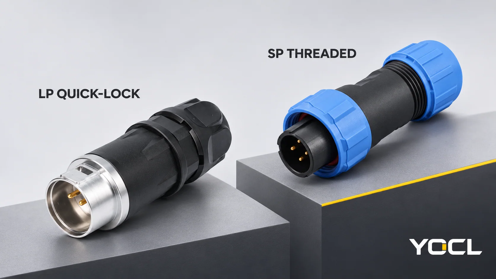
LP uses a pushbutton snap lock; SP uses threaded coupling. Choose between them by checking the specified mating pair and the space needed to operate it, after confirming the electrical configuration, wire termination and cable seals. A quick-lock connection may suit a service layout with accessible button release. A threaded connection may suit a layout with accessible collar operation. Either choice remains unconfirmed if the required parts, access or protection conditions are missing.
The locking names do not establish that LP and SP can mate, that one is more waterproof, or that either may be disconnected under load. This comparison concerns the actual YOCL ranges; do not assume another manufacturer’s similarly named products share their dimensions or interfaces.
Start with the same connection and service requirements
The YOCL LP range describes pushbutton snap locking with screw-clamp wire termination. The SP range describes threaded mating, with termination options that vary by series and insert. Compare them against one declared duty, rather than comparing the highest number printed anywhere in each range.
| Requirement | LP quick-lock candidate | SP threaded candidate | What decides the choice? |
|---|---|---|---|
| Lock and release access | Reach the designated pushbutton and retain access to the bodies | Reach and grip the designated coupling collar | The actual installed hand/tool and body-access envelope |
| Separating the pair | Space to withdraw the matching halves after release | Space to withdraw the matching halves after uncoupling | Available movement and cable routing, not just mated length |
| Wire termination | Listed LP products use screw clamps | Exact SP configuration may use solder or another listed method | Harness construction, conductor acceptance and model instructions |
| Electrical duty | Use one exact contact configuration | Use one exact contact/termination configuration | Required current, voltage and conductor size together |
| Cable entry | Match the selected body’s individual cable-seal range | Select the stated seal option for the body | Actual jacket diameter, independently of conductor area |
| Panel installation | Select the particular socket format and drawing | Select the particular socket format and drawing | Cutout, fixing, panel thickness and internal space |
| Environmental protection | LP range states IP68 in the connected state | SP catalogue states IP68; confirm the required assembly state and conditions | Evidence for the actual configuration and exposure |
The comparison has four possible outcomes: LP, SP, either, or neither yet. A locking preference cannot overrule a failed electrical, sealing or mounting requirement.
Coupling, termination and cable-entry tightening are different operations
The mating coupling secures the two connector halves. The wire termination joins each conductor to its contact. The rear cable-entry components act on the jacket/sealing arrangement. A panel socket may also have a separate mounting nut or flange.
For LP, “quick-lock” describes mating. It does not mean the screw-clamp wire termination needs no preparation or tools. For SP, “threaded coupling” describes the mating collar; it is not an instruction to turn every threaded part on the connector during disconnection.
Identify the intended control on the exact drawing. Do not release a cable-entry nut when the intended service action is to separate the mating pair. Wiring and assembly follow the selected configuration’s instructions; this comparison supplies no generic screw torque, soldering procedure or seal compression setting.
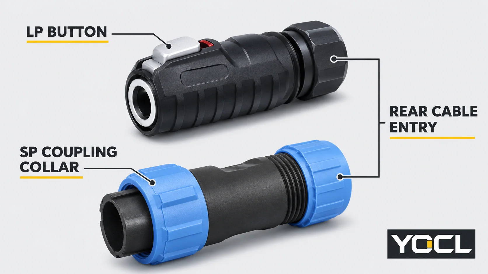
Compare access to the control and space to withdraw the connector
An LP button must remain reachable
For an LP proposal, locate the release button on the selected format and show its orientation in the equipment layout. Can it be reached after adjacent connectors, guarding and cable supports are present? Can the operator hold the bodies and separate them without relying on cable tension?
A short catalogue length alone does not answer those questions. A connector can fit in the mated position while its release control is inaccessible. Where access is unresolved, keep the LP choice pending a layout or representative fit check rather than assuming “quick-lock” guarantees easy servicing.
An SP collar needs its own working envelope
For an SP proposal, identify the mating collar separately from the rear entry nut and panel fixing. Check access around that collar, the approach for operating it and the movement needed to separate the halves. A nearby panel lip or a closely packed connector row may determine the practical result.
Do not assign a universal clearance or number of turns from the SP family name. Use the selected body’s instructions and layout. Threaded coupling alone does not establish better vibration performance, a stronger connection or a longer service life than an LP candidate; those claims need applicable evidence.
Both choices still need axial movement and a cable route
After unlocking, the halves must have space to separate along their intended mating path. Include the cable’s routing requirements and the surrounding support arrangement. Neither coupling method removes those needs.
If the layout allows collar operation but blocks the LP button, SP may be the more workable candidate. If it allows the LP control and withdrawal but makes the proposed SP collar inaccessible, LP may be more workable. If both controls are accessible and the remaining requirements are met, either may remain eligible. If neither can be serviced in the layout, revise the arrangement or choose another format.
Actual LP-12 and SP13 configurations change more than the lock
The following current catalogue examples make the specification differences concrete. They compare two listed configurations, not the effect of coupling method on performance.
| Field | LP-12 listed two-contact configuration | SP13 listed two-contact configuration |
|---|---|---|
| Mating mechanism | Pushbutton snap lock | Threaded locking |
| Wire termination | Screw clamp | Solder |
| Rated current | 5 A | 13 A |
| Voltage declaration | 125 V | 250 V AC working voltage |
| Conductor section | 0.34–0.5 mm² | Maximum 2.0 mm² |
| Cable jacket range | 3.5–4.5 mm | Type I: 4–6.5 mm; Type II: 5–8 mm |
Sources: LP-12 product information and SP13 product information, checked November 3, 2026. These are first-party declarations, not an independent comparison test. The SP13 maximum conductor figure is not a complete lower-to-upper acceptance range.
The wider ranges contain other configurations. In particular, do not assign the SP13 two-contact values to every SP13 insert. Its four-contact row instead lists 5 A, 200 V AC and a maximum 0.75 mm² conductor section. Keep the current, working voltage and wire limit from the same row. Likewise, an LP-12 example does not establish the limits of LP-16, LP-20 or LP-24.
Requirement case 1: electrical and cable inputs eliminate the smaller example
Consider hypothetical requirements for a two-contact 24 V DC connection carrying 8 A, with a 1.5 mm² conductor and 6.0 mm cable jacket.
The listed LP-12 candidate fails several independent checks: 8 A exceeds its 5 A declaration, 1.5 mm² is outside its conductor range, and 6.0 mm exceeds its jacket range. An accessible release button cannot repair those mismatches. Reassess another exact connector configuration rather than accepting LP-12 for its locking convenience.
SP13’s two-contact current declaration and listed seal options warrant further review, but do not complete approval. Its stated working voltage is AC, its conductor value is a maximum, and the proposed duty is DC. Obtain confirmation of DC suitability, actual conductor acceptance, terminations and the exact pair before choosing it. The supported outcome here is reject the LP-12 example; hold the SP13 proposal for defined checks, not “SP is universally better.”
Requirement case 2: suitable ratings do not resolve operation space
Consider another hypothetical layout in which the proposed electrical, cable, mounting and environmental requirements have been confirmed for both candidates. The SP collar is reachable, but the proposed LP button would face an obstruction after installation.
That layout favours retaining the accessible SP proposal or revising the LP mounting orientation/format. It does not prove all SP connectors need less space. Repeat the access check on the exact proposed bodies, including the withdrawal movement. The case is a layout decision, not a measured field result.
Specify the actual pair, not just LP, SP or a contact count
For either family, record both component identities, body formats, contact count, complementary contacts and circuit assignment. Similar shell diameters or the same number of contacts do not establish cross-family compatibility. Neither the LP nor SP range claims that its different sizes can be freely mixed.
YOCL’s LP-12 table, for example, identifies LP-12-C02PE-11-001 as a male-contact cable plug and LP-12-J02SX-11-101 as a female-contact single-hole panel socket. This demonstrates why contact gender and body format must both appear in the record. Obtain confirmation that the complete proposed pair and its wiring assignment meet the requirement; do not treat the naming example as a universal replacement approval.
For SP13, SP1310/P identifies a pin-contact cable-plug body designation. The page identifies SP1311, SP1312 and SP1313 as corresponding inline or panel formats, with complementary P/S contacts and matching contact arrangement required. Those body designations still leave the contact count and cable-seal choice to specify. Type I is not marked in the catalogue designation, so state the seal range explicitly.
For the broader distinction between a detachable pair and a fixed inline joint, use the waterproof connector overview. An openable cable joint is not automatically another mating half for either family.
Verify protection and the permitted service condition separately
LP’s published IP68 statement applies in the connected state. For a proposal requiring protection while disconnected or capped, obtain evidence for that specific state. SP’s IP68 catalogue statement also needs the selected configuration, assembly state and exposure conditions identified before it can answer the application’s requirement.
IEC 60529 provides a classification of enclosure protection, as stated in its official public catalogue scope. That classification is not evidence that a loose connector, an arbitrary cable or an altered panel installation has been tested. The source does not certify either YOCL family.
Specify actual water exposure and the evidence required for the completed assembly. A threaded collar is not automatically more watertight than a snap lock, and neither label establishes unlimited immersion. Keep the cable-entry seal, mating interface and panel joint within their documented arrangements.
Also confirm the electrical state allowed for mating and disconnection. A detachable format or current-carrying rating does not, by itself, grant load-breaking permission. Plan servicing through the equipment’s isolation procedure and selected connector instructions; this article does not authorize energized disconnection.
Record the LP or SP choice as a complete connection
A useful pair record contains:
| Record item | Required information |
|---|---|
| Both halves | Complete proposed part references; body format; contact count and complementary contact types |
| Circuit | Current, working voltage including AC/DC, conductor details and contact assignment |
| Harness work | Exact screw/solder/crimp termination and its instructions; no family-wide substitution |
| Cable entry | Jacket diameter and the explicit seal option for each cable-terminated body |
| Equipment layout | Socket drawing, panel requirements, button/collar access, withdrawal space and cable route |
| Service and protection | Permitted electrical state; connected/disconnected/capped protection where required; exposure evidence |
Choose LP when its exact configuration meets the duty and the button/release arrangement suits the service layout. Choose SP when its exact configuration meets the duty and its collar can be operated in that layout. Keep either when both satisfy the same requirements; keep neither yet when a critical field is unconfirmed.
For a YOCL comparison request, send this record with the two proposed configurations and quantities. Ask for the mating-pair confirmation and the documents needed to close the specific unresolved fields, rather than requesting a generic “waterproof quick connector.”
Related reading: See lever and push-in wire connector comparison.
Related reading: understanding heavy-duty connector assemblies.
References
- YOCL product information, LP Quick-Lock Waterproof Connectors — range coupling, termination, formats and connected-state protection; checked November 3, 2026.
- YOCL product information, SP Waterproof Circular Connectors — threaded coupling and configuration-dependent termination/mounting choices; checked November 3, 2026.
- YOCL product information, LP-12 Quick-Lock Waterproof Circular Connectors — two-contact specification, ordering examples and original external drawings; checked November 3, 2026.
- YOCL product information, SP13 Waterproof Circular Connectors — contact-specific ratings, body/mating designations, cable seals and original exterior references; checked November 3, 2026.
- International Electrotechnical Commission, IEC 60529 consolidated edition 2.2 — Degrees of protection provided by enclosures — public catalogue classification scope only; no full-standard or model-conformity assessment.