
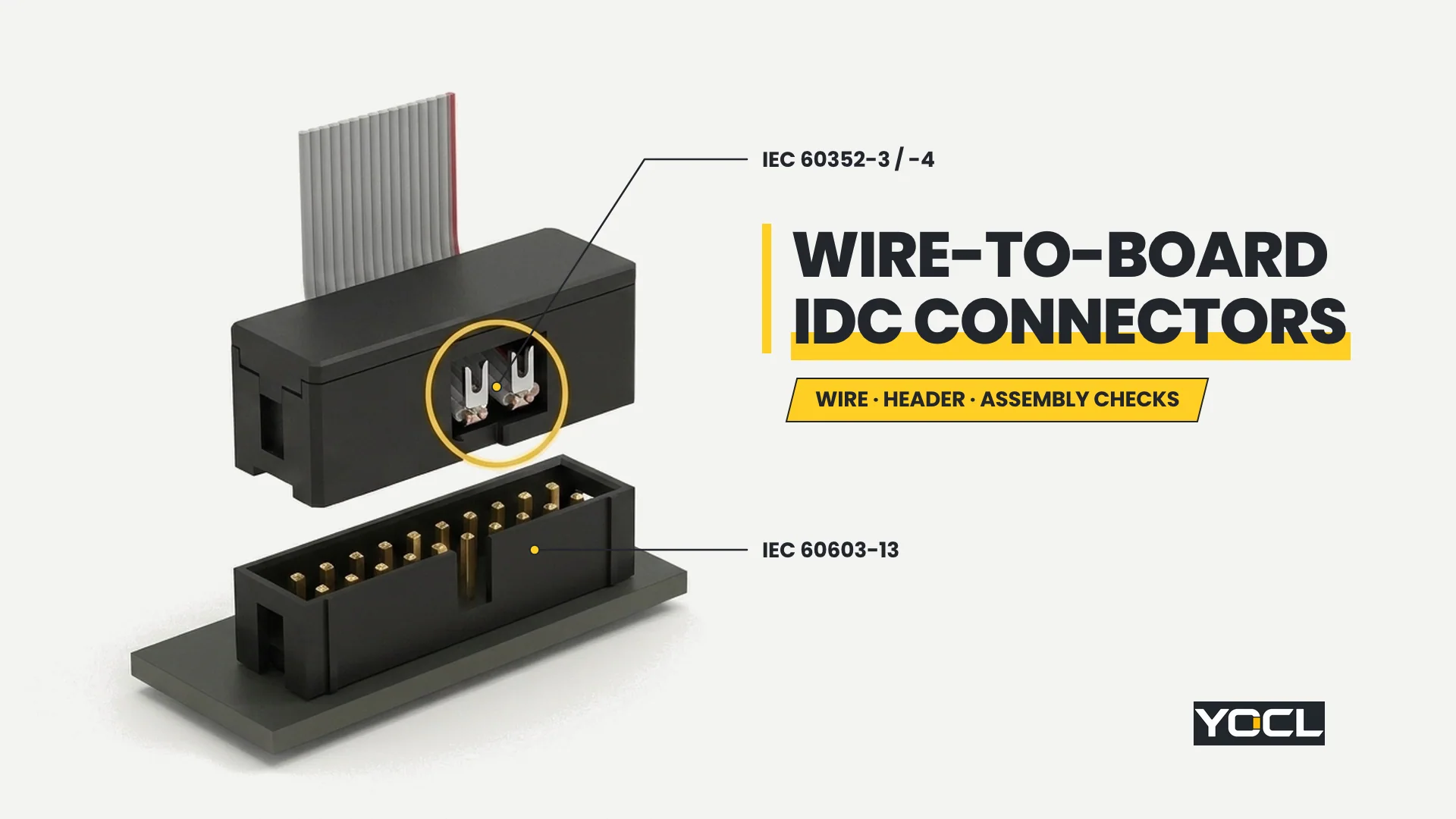
Wire-to-board IDC connectors terminate insulated conductors directly to a printed circuit board without pre-stripping by forcing each wire into a precision-slotted metal beam. Reliable service under IEC 60352-3, IEC 60352-4, and IPC/WHMA-A-620 depends on three linked verification gates: matching wire geometry to the slot, confirming header pitch and keying, and verifying parallel press assembly.
Skipping wire stripping makes insulation displacement termination fast for multi-conductor flat ribbon cables and compact discrete-wire harnesses, yet the same mechanism leaves very little margin for substitution. A conductor one gauge too small loses gas-tight normal force, a conductor one gauge too large shears strands or cracks the housing, and an unkeyed header allows a 180-degree reversal that damages downstream electronics on first power-up.
How Wire-to-Board IDC Connectors Form a Gas-Tight Contact
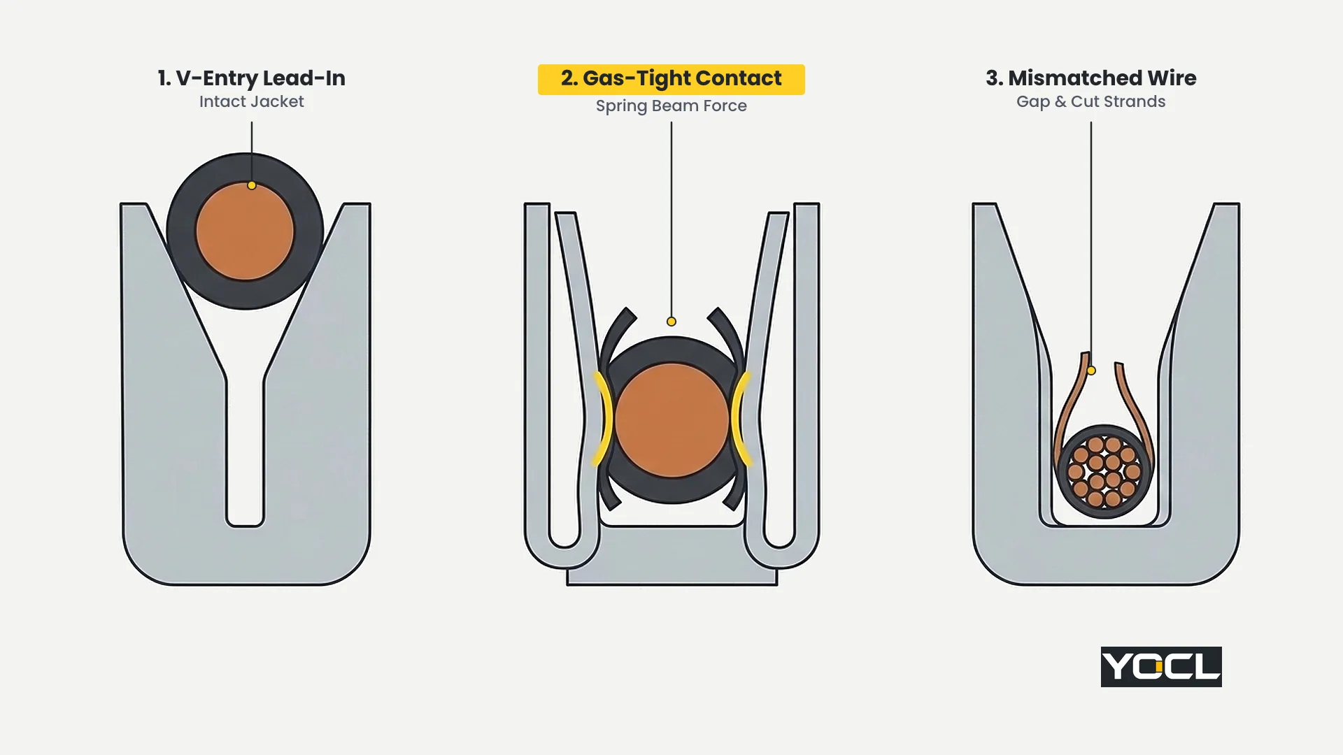
Wire-to-board IDC connectors establish an electrical and mechanical joint when an unstripped conductor is pressed perpendicular into a calibrated U-shaped metal slot whose sharp inner edges slice through the insulation and plastically deform the copper surface. Under IEC 60352-3 and IEC 60352-4, the deflected spring beams must maintain continuous normal force so the metal-to-metal interface remains gas-tight against oxidation and vibration.
The IEC 60352 series splits insulation displacement connections into two distinct qualification scopes based on whether the contact interface can be probed after assembly:
- IEC 60352-3 (accessible ID connections) covers discrete or open-frame IDC contacts where probes can reach the termination for measurement, spanning solid round conductors from 0.25 mm to 3.6 mm nominal diameter and stranded conductors from 0.05 mm² to 10 mm² cross-sectional area.
- IEC 60352-4 (non-accessible ID connections) covers enclosed IDC housings—including standard multi-way ribbon sockets and covered discrete wire-to-board plugs—where the contact slot sits inside a latched plastic body and cannot be probed directly without destroying the termination.
Because the metal slot performs both insulation cutting and spring clamping in one fixed geometry, an IDC socket behaves very differently from a crimped barrel or a screw clamp. For a broader map of how IDC sits alongside crimp, lever, and screw technologies, see what is a wire connector. When an application requires stripped conductors with higher current capacity or custom strand bundles, compare crimp vs solder wire terminals or move the board interface to a terminal block instead of forcing an out-of-spec wire into an IDC slot.
Wire Checks: Matching Conductor Gauge, Stranding, Insulation and Pitch
Wire checks verify that conductor cross-section, strand construction, insulation outer diameter, insulation compound, and flat-cable pitch all fall inside the exact limits published on the wire-to-board IDC connector datasheet. Unlike screw clamps or wide-range crimp barrels, an IDC beam slot is stamped to a single narrow interference window where even one AWG step or an overly hard jacket compromises gas-tight contact.
Before cutting a single harness length, confirm all five wire parameters against the connector manufacturer specification:
| Wire Parameter | What Must Match the Connector Spec | Failure Mode if Mismatched | Pre-Assembly Verification Check |
|---|---|---|---|
| Conductor size (AWG / mm²) | Exact rated gauge or narrow 2-gauge window (for example 28 AWG / 0.08 mm² on standard 1.27 mm ribbon) | Undersized wire loses spring normal force and drifts high-resistance; oversized wire shears strands or splits the housing | Measure conductor diameter or confirm spool markings against the connector drawing before kitting |
| Conductor construction | Approved solid or stranded class (such as 7-strand tinned copper for flat ribbon) | Using solid wire in a stranded-only slot over-stresses the beams; fine-strand flexible wire can splay out of the slot | Check whether the datasheet explicitly lists solid, stranded, or both for that exact contact part number |
| Insulation outer diameter (mm) | Maximum and minimum jacket OD for both the slot lead-in and the housing strain-relief channel | Oversized insulation jams the housing cover or prevents full seating; undersized insulation slips under strain relief | Measure overall wire OD with calipers across at least three points on the spool |
| Insulation material | Approved soft or semi-rigid thermoplastic (typically PVC or specified TPE/PTFE grade) | Hard cross-linked or fluoropolymer jackets resist blade piercing or leave cold-flow debris inside the contact zone | Verify jacket compound code against the connector application specification |
| Ribbon cable pitch (mm) | Exact center-to-center conductor pitch (1.27 mm for 2.54 mm dual-row headers, or 1.00 mm / 0.635 mm fine pitch) | Cumulative pitch drift pushes outer conductors off-center, causing missed contacts or adjacent shorts | Lay the cut ribbon across the connector guide grooves and check alignment at both Pin 1 and the last pin |
Choose a matching ribbon or discrete wire spool whose conductor gauge, strand construction, and maximum insulation OD all sit strictly inside the connector datasheet window; switch to a crimp-and-housing wire-to-board system whenever the circuit requires heavy-wall insulation, ultra-fine flexible stranding, or mixed gauges inside the same connector.
Pay special attention to two frequent wire preparation mistakes:
- Never pre-strip or solder-tin wire ends for IDC termination. Stripping removes the jacket that centers the conductor in the cover and engages the strain-relief channel. Dip-tinning stranded wire with solder creates a rigid slug that resists blade displacement and creeps under sustained spring pressure—the same cold-flow mechanism explained in tinned stranded wire in terminal blocks.
- Do not substitute metric and AWG ribbon pitches casually. A 1.27 mm pitch ribbon cable and a 1.25 mm pitch cable look identical across two conductors, yet across a 20-way connector the cumulative 0.02 mm error per pitch reaches 0.38 mm—enough to push outer conductors into the edge of the U-slot beam and shear strands during pressing.
Header Checks: Pitch, Shrouding, Polarization and Pin-1 Mapping
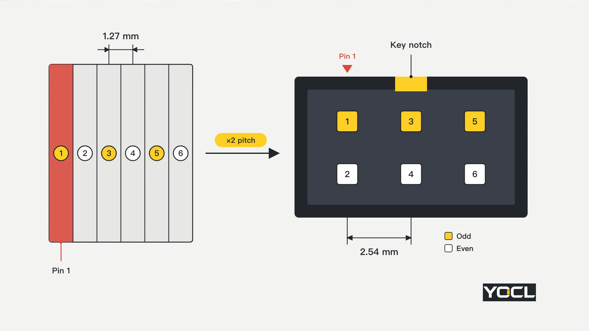
Header checks confirm that the PCB-mounted male header matches the wire-to-board IDC socket in grid pitch, pin count, shroud clearance, polarization keyway, Pin-1 orientation, and contact plating. For the widely used 2.54 mm (0.100 in) dual-row ribbon system governed by IEC 60603-13 and DIN 41651, every 1.27 mm pitch ribbon conductor maps alternately into the two staggered 2.54 mm pin rows so odd conductors land on one row and even conductors land on the opposite row.
Understanding that 1.27 mm to 2.54 mm staggered mapping prevents one of the most common board-layout errors: reversing odd and even signals or flipping the entire bus by 180 degrees. On a standard IEC 60603-13 box header, the molded Pin-1 triangle on the IDC socket aligns with the red edge stripe on conductor 1 of the flat ribbon cable and mates into Pin 1 of the shrouded PCB header, while the central polarization bump on the socket slides into the notch on the header shroud.
Selecting the right PCB header style determines how well the mated assembly resists reversed insertion, accidental unplugging, and board-edge clearance collisions:
| Header Feature | Shrouded Box Header | Unshrouded Pin Header | Ejector-Latch Box Header | Mating Verification Check |
|---|---|---|---|---|
| Mechanical keying | Center polarization notch (plus optional side slots) blocks 180-degree reversal | None; socket can mate backwards or shifted by one column | Center polarization notch plus locking ears | Confirm the socket polarization bump matches the header notch width and position |
| Retention under vibration | Friction fit between contacts and shroud walls | Contact friction only; prone to walk-out under shock | Positive mechanical latches lock over the socket body | Verify latch length matches whether a strain-relief bar is installed on the socket |
| PCB footprint and clearance | Larger outline than bare pins due to shroud walls | Minimal footprint for tight boards | Requires extra side clearance for latch swing during unmating | Check 3D mechanical keep-out zones around tall capacitors or enclosure walls |
| Contact plating match | Gold-over-nickel or tin-over-nickel | Gold-over-nickel or tin-over-nickel | Gold-over-nickel or tin-over-nickel | Match gold to gold and tin to tin to avoid galvanic corrosion and fretting wear |
Choose a shrouded box header with a center polarization notch for every production wire-to-board IDC interface, and add ejector latches whenever the assembly sees vibration, overhead mounting, or repeated service cycles; reserve unshrouded pin headers strictly for temporary bench test points where reversal is impossible or non-destructive.
Two subtle header mismatches still slip past BOM reviews even when pitch and pin count match:
- Short vs long ejector latches: A box header with short latches fits an IDC socket without a strain-relief bar, whereas adding a snap-on strain relief increases the socket stack height and requires long latches to engage cleanly.
- Mixed gold and tin plating: Mating a tin-plated IDC socket onto a gold-plated PCB header—or the reverse—accelerates fretting corrosion under micro-motion and thermal cycling, raising contact resistance over months of field operation.
Assembly Checks: Tooling, Seating, Strain Relief and Electrical Verification
Assembly checks verify that the wire-to-board IDC connector has been cut square, pressed evenly with controlled shut height, fitted with proper strain relief, and electrically tested for continuity and isolation before mating to a live board. Under IPC/WHMA-A-620 Section 6, visual workmanship inspection alone never proves a gas-tight electrical termination; every production lot requires both physical inspection and electrical continuity verification.
Standard bench vices or slip-joint pliers apply uneven angular force across multi-way housings, cracking plastic latches on one side while leaving contacts half-seated on the other. Always use a dedicated parallel-action IDC press or manufacturer-approved discrete-wire punch tool with the matching die platen for the connector series.
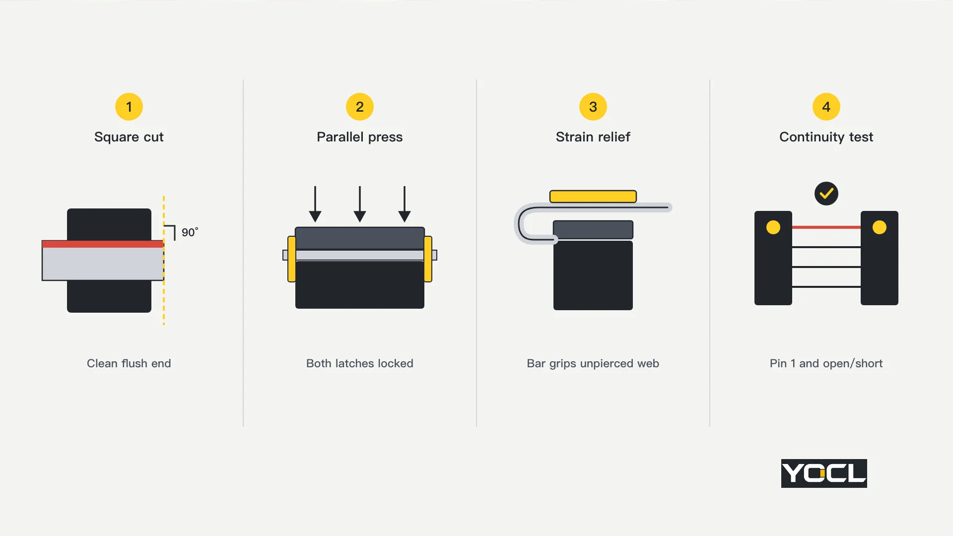
Use the following post-termination inspection matrix based on IPC/WHMA-A-620 Section 6 principles to separate acceptable assemblies from defects that require scrap and re-termination:
| Inspection Point | Acceptable Condition | Defect Condition (Reject / Scrap) | Corrective Action |
|---|---|---|---|
| Ribbon end cut and overhang | Clean 90-degree perpendicular cut; conductors sit flush or within the drawing overhang limit without exposed ragged strands | Skewed cut leaving outer conductors short of the slot, split web entering the contact zone, or excessive overhang risking shorts | Replace dull guillotine shear blades and re-cut square using a fixed 90-degree fence |
| Cover seating and side latches | Upper cover sits parallel to the base housing with both end latches fully engaged and zero visible gap | Crooked cover, partially popped latch, or cracked/whitened plastic around the IDC towers | Verify press shut-height calibration and match the platen adapter to the exact connector width |
| Strain-relief engagement | Ribbon folds smoothly 180 degrees over the cover; strain-relief bar snaps fully into side hooks and grips unpierced insulation | Bar unlatched, cracked, or pinching directly over the active pierced contact zone | Confirm ribbon thickness and correct strain-relief part number for the socket body |
| Electrical continuity and isolation | End-to-end continuity on every circuit (including Pin 1 to Pin 1 verification) and zero pin-to-pin shorts | Open circuit, intermittent reading during gentle flex, swapped odd/even mapping, or adjacent short | Cut off the faulty end and terminate a new connector; never re-press a damaged socket |
Pass an IDC harness only when all four gates—square cut, parallel latched housing, intact strain relief, and 100-percent electrical continuity and isolation testing—succeed together; reject and replace any assembly showing a cracked tower, skewed conductor, or popped latch rather than attempting to pry open and reuse the connector.
Reusability is a critical boundary rule for IDC assemblies. Opening a latched IDC socket and pressing it onto a second cable—or re-pressing the same pierced section of ribbon—relaxes the spring beams and tears pre-cut insulation, destroying the gas-tight interface required by IEC 60352-4. For field-serviceable wire-to-wire junctions that must be opened and re-wired without tools or replacement housings, use reusable clamping connectors instead; see lever vs push-in wire connectors.
When Not to Use Wire-to-Board IDC Connectors
Wire-to-board IDC connectors excel at low-current signal, logic, sensor, and internal control-board interconnections, but they become a reliability liability when pushed outside their mechanical and electrical envelope. Switching to a different termination technology up front is far cheaper than chasing intermittent field faults later.
Avoid wire-to-board IDC connectors and specify an alternative interface in four common scenarios:
- Higher-current power distribution: Standard 1.27 mm / 2.54 mm IDC contacts carry low signal currents (typically 1 A to 3 A per contact depending on the datasheet); higher-current board feeds belong on crimp wire-to-board power housings or PCB terminal blocks.
- Frequent field re-wiring by technicians: Because IDC sockets are single-termination components requiring matched press tooling, panels that need field wire changes should transition to screw or spring-clamp terminal blocks.
- Heavy unguided cable pull or continuous flexing: Flat ribbon cables and compact discrete IDC beams rely on enclosure routing and strain-relief bars to isolate the U-slot from pull forces; dynamic drag-chain or external umbilical cables require circular or heavy-duty crimped connectors with dedicated cable glands.
- Uncontrolled or mixed wire gauges in the same plug: If a harness mixes signal and power wire sizes in one connector footprint, a crimp-contact housing lets each cavity accept its matched terminal barrel rather than forcing one fixed IDC slot width to fit every wire.
Frequently Asked Questions
Can you reuse an IDC connector after removing the ribbon cable?
No, standard wire-to-board IDC sockets should be treated as single-use terminations. Once the U-slot beams have deflected around a conductor and the housing latches have been pried open, beam spring force and plastic latch retention both degrade. Always cut back past the pierced wire section and press a new connector onto fresh cable.
Can you use stranded wire in every wire-to-board IDC connector?
No, stranded compatibility depends on the exact contact slot design. Some discrete wire-to-board IDC contacts are qualified only for solid conductors, while others accept specific stranded constructions such as 7-strand tinned copper. Always confirm both the conductor class and the approved AWG range on the connector datasheet before assembly.
Why does a 2.54 mm IDC box header use 1.27 mm pitch ribbon cable?
A standard 2.54 mm IDC box header arranges its pins in two parallel rows spaced 2.54 mm apart along each row. Inside the mating IDC socket, the insulation displacement contacts stagger alternately between the two rows, so adjacent ribbon conductors spaced at 1.27 mm map cleanly onto odd and even pins because 1.27 mm multiplied by 2 equals 2.54 mm.
Do you need a dedicated parallel press to terminate wire-to-board IDC connectors?
Yes, a dedicated parallel-action IDC press with the correct platen adapter is strongly recommended for reliable terminations. Pliers or bench vices apply uneven angled pressure that cracks housings, leaves end latches unseated, and skews conductors inside the U-slots, leading to intermittent opens or adjacent pin shorts under thermal cycling and vibration.
References
- IEC 60352-3:2020 — Solderless connections – Part 3: Accessible insulation displacement (ID) connections – General requirements, test methods and practical guidance (International Electrotechnical Commission).
- IEC 60352-4:2020 — Solderless connections – Part 4: Non-accessible insulation displacement (ID) connections – General requirements, test methods and practical guidance (International Electrotechnical Commission).
- IEC 60603-13:1995 (DIN 41651) — Connectors for frequencies below 3 MHz for use with printed boards – Part 13: Detail specification for two-part connectors of assessed quality, for printed boards for basic grid of 2.54 mm (0.1 in), with free connectors for non-accessible insulation displacement terminations (ID) (International Electrotechnical Commission).
- IPC/WHMA-A-620 — Requirements and Acceptance for Cable and Wire Harness Assemblies, Section 6: Insulation Displacement Connection (IPC / Wiring Harness Manufacturer Association).
- YOCL ELECTRIC — What Is a Wire Connector?
- YOCL ELECTRIC — Crimp vs Solder Wire Terminals
- YOCL ELECTRIC — What Is a Terminal Block?
- YOCL ELECTRIC — Tinned Stranded Wire in Terminal Blocks
- YOCL ELECTRIC — Lever vs Push-In Wire Connectors