
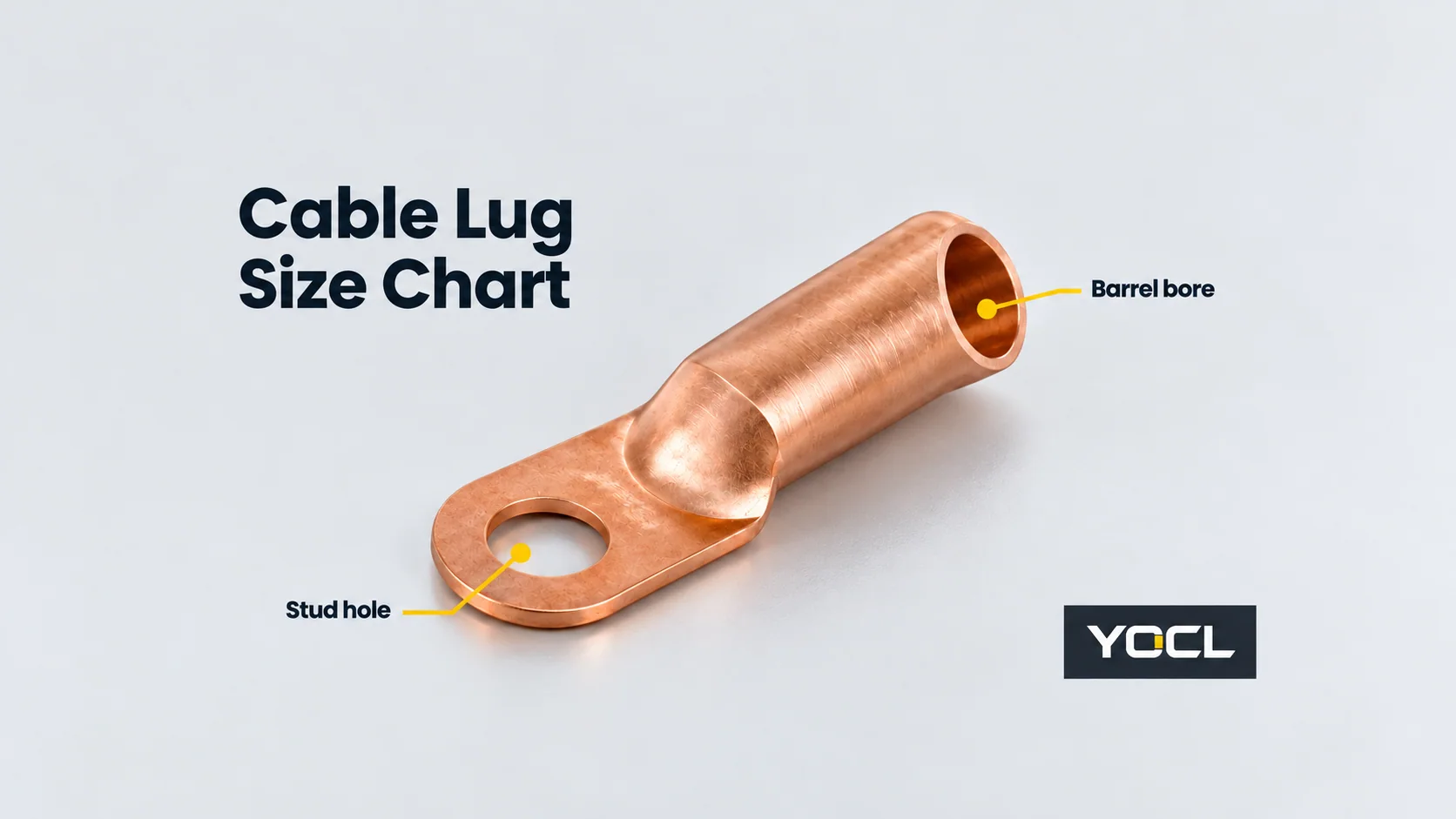
A cable lug size chart involves three separate specifications: nominal conductor area in mm², barrel bore in mm, and mounting-hole diameter in mm. Match the conductor specification first, then check the exact lug series against the equipment terminal and available space. A model number or a cable that physically enters the barrel does not establish an approved connection.
This reference provides the published YOCL DT single-hole copper lug dimensions and a method for checking conductor compatibility. The DT product page does not explicitly list rated conductor areas, so the model suffixes below are retained as identifiers—not converted into confirmed mm² ratings.
Read the units before choosing a row
| Specification | Unit or format | What to obtain | What it does not establish |
|---|---|---|---|
| Nominal conductor area | mm²; retain AWG if specified | Cable datasheet or conductor marking, plus material and construction | Lug bore diameter or permissible current by itself |
| Approved lug conductor size | Manufacturer’s stated area or size range | Exact-model conductor compatibility document | Approval from the model suffix alone |
| Barrel bore, d | mm | Lug drawing and dimension table | Compatibility with every conductor that can enter it |
| Barrel outside diameter, D | mm | Lug drawing and dimension table | Cable cross-sectional area |
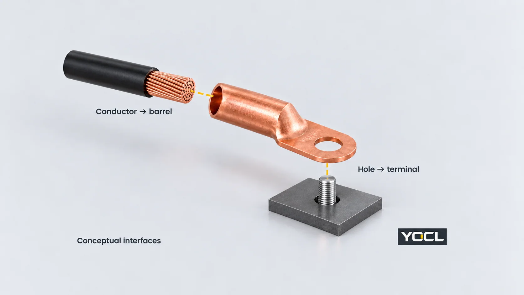
| Mounting hole, Φ | mm | Exact lug hole option and mating-terminal drawing | A threaded hole or the nominal bolt designation |
| Barrel cavity length, L1 | mm | Exact series section drawing | Strip length, die position or crimp count without instructions |
| Overall length L and palm width B | mm | Lug drawing and available terminal envelope | Electrical clearance or assembly approval |
Conductor area is an area, not a diameter. For example, a cable specified as 35 mm² has a nominal conductor-area designation; it does not have a 35 mm barrel requirement. Record whether the conductor is copper or aluminium and its construction/class. The official scope of IEC 60228:2023 addresses nominal cross-sectional areas and different conductor constructions, including solid, stranded and flexible conductors. Its public abstract is not a lug compatibility chart.
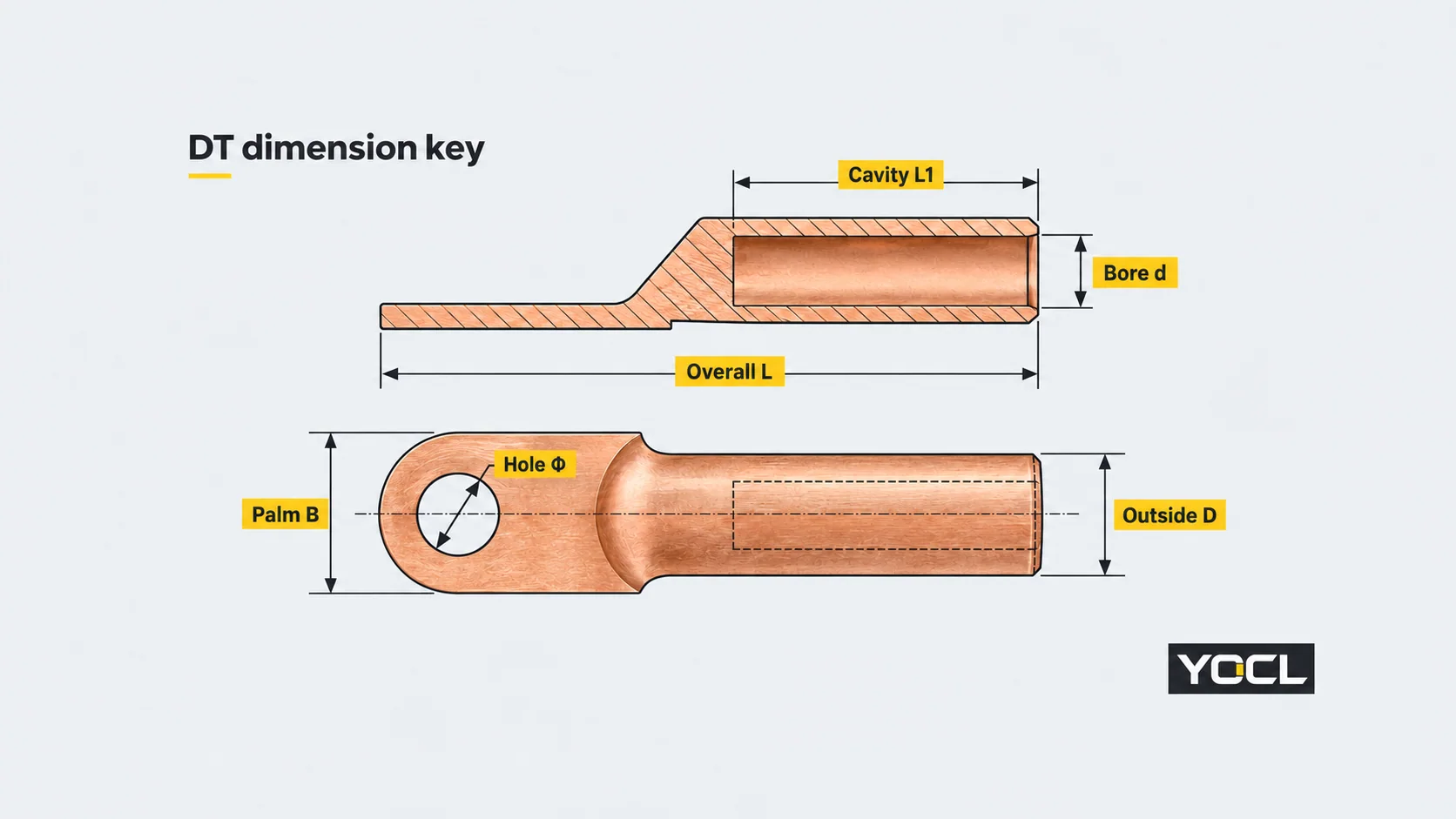
YOCL DT cable lug dimension chart
Scope: DT single-hole copper lugs, DT-10 through DT-630. All numerical dimensions below are millimetres. Source: the YOCL DT product table and dimension drawing, checked 11 October 2026. The drawing shows d as the barrel cavity diameter and L1 as its axial length.
Conductor-area status for every row: not explicitly rated in the cited public table; obtain exact-model confirmation. This is a mechanical dimension chart, not an area-to-lug approval table or a chart for DT(G), DT-2, SC, JG or AUS series.
| DT model | Hole Φ (mm) | Barrel outside D (mm) | Barrel bore d (mm) | Cavity L1 (mm) | Overall L (mm) | Palm B (mm) |
|---|---|---|---|---|---|---|
| DT-10 | 8.5 | 9 | 6 | 33 | 62 | 16 |
| DT-16 | 8.5 | 10 | 6.5 | 36 | 68 | 16 |
| DT-25 | 8.5 | 11 | 7.5 | 38 | 72 | 18 |
| DT-35 | 10.5 | 12 | 8.5 | 41 | 76 | 20 |
| DT-50 | 10.5 | 14 | 10 | 46 | 84 | 23 |
| DT-70 | 12.5 | 16 | 11.5 | 49 | 95 | 26 |
| DT-95 | 12.5 | 18 | 13.5 | 53 | 102 | 28 |
| DT-120 | 14.5 | 20 | 15 | 56 | 109 | 30 |
| DT-150 | 14.5 | 22 | 17 | 60 | 117 | 34 |
| DT-185 | 16.5 | 24 | 19 | 62 | 124 | 37 |
| DT-240 | 16.5 | 27 | 21 | 67 | 131 | 40 |
| DT-300 | 21 | 30 | 23.5 | 70 | 141 | 45 |
| DT-400 | 21 | 34 | 26.5 | 75 | 155 | 49 |
| DT-500 | 21 | 38 | 29 | 77 | 180 | 55 |
| DT-630 | 21 | 45 | 35 | 84 | 210 | 59 |
The table identifies possible mechanical candidates. It does not specify current rating, crimp tooling, tightening torque, or the permitted conductor class. Those belong to the exact connector and equipment documentation.
Worked lookup: DT-35 and a constrained terminal space
Suppose a design specifies a 35 mm² copper conductor and an equipment drawing calls for a 10.5 mm lug clearance hole, with an overall lug envelope no longer than 80 mm and no wider than 22 mm. These are illustrative design inputs, not a universal rule for 35 mm² cables.
The DT-35 row gives:
- Hole Φ: 10.5 mm, matching the stated hole requirement.
- Overall L: 76 mm, leaving 4 mm against the 80 mm envelope.
- Palm B: 20 mm, leaving 2 mm against the 22 mm envelope.
- Barrel bore d: 8.5 mm; outside diameter D: 12 mm; cavity L1: 41 mm.
The result is a mechanical candidate, pending conductor and tooling confirmation. The 35 mm² cable input and the DT-35 identifier are not, by themselves, evidence of an approved match. Ask for the permitted conductor area and construction, then the specified tool/die combination. The 4 mm and 2 mm differences are envelope arithmetic, not required electrical clearances.
The next listed model, DT-50, has L = 84 mm and B = 23 mm, so it exceeds both assumed envelope limits. Moving to a larger barrel is not an automatic solution. If DT-35 is unsuitable for the conductor, investigate another documented series or change the assembly design.
Stud size and hole diameter: keep both on the order
An M10 designation describes a metric thread size; a listed 10.5 mm dimension describes the lug hole. They are different fields. The worked example uses an equipment drawing that explicitly requests the 10.5 mm hole—it does not derive that requirement solely from an M10 bolt label.
Specify the terminal’s nominal stud/bolt size and the required lug-hole diameter or hole option. Verify seating and clamping against the equipment drawing. Do not enlarge a hole or treat a larger listed hole as automatically acceptable.
Some other YOCL series list a Φ range rather than one hole diameter. Their product pages describe this as a range of available hole options, not an adjustable hole or a promise that every intermediate diameter is supplied. For two-hole lugs, also match the hole-centre spacing; DT single-hole dimensions cannot answer that task. See DT-2 two-hole copper lugs for its separate geometry.
Why the exact series matters even when the model code looks familiar
YOCL lists both DIN AUS and AUS Thickened copper lugs. Their public AUS-25 rows have these dimensions:
| Published series and model | Hole options Φ (mm) | Outside D (mm) | Bore d (mm) | Overall L (mm) | Palm B (mm) |
|---|---|---|---|---|---|
| DIN AUS, AUS-25 | 8.4–10.5 | 10.5 | 8 | 50.5 | 17 |
| AUS Thickened, AUS-25 | 8.4–10.5 | 10 | 7.3 | 50.5 | 17 |
Sources: DIN AUS copper lugs and AUS Thickened copper lugs. Although the identifier, hole range, length and palm width match, the barrel dimensions differ. Do not merge the two tables or assume a shared code permits substitution. Neither cited row explicitly establishes a rated conductor area.
Likewise, an approximate AWG-to-mm² conversion can assist unit comparison but does not authorize replacing one specified conductor size with another. If the cable is specified in AWG, retain that designation in the compatibility request instead of rounding it to a convenient metric model suffix.
Information to confirm before ordering
Send these inputs when discussing the YOCL cable lug range:
- Cable specification: copper or aluminium, nominal mm² or AWG, conductor construction/class and cable datasheet.
- Exact lug identity: series and complete model; requested conductor rating or permitted range.
- Equipment interface: stud/bolt designation, required hole diameter, and hole pitch if two-hole.
- Space envelope: allowable overall length, palm width, and the terminal arrangement drawing.
- Termination documentation: specified crimp tool/die, conductor preparation instructions and equipment fastening requirements.
If conductor compatibility or termination instructions are unavailable, keep the row as a dimensional candidate rather than an installation-approved selection. For broader decisions between copper, aluminium, bimetallic, mechanical and pin formats, use What Is a Cable Lug? Types, Materials and Connection Interfaces.
References
- IEC 60228:2023 — Conductors of insulated cables: official public scope/abstract for conductor areas and constructions; no paywalled diameter tables are reproduced.
- YOCL DT copper cable lugs: first-party dimensions and section drawing used for the DT lookup.
- YOCL DIN AUS copper cable lugs and YOCL AUS Thickened copper cable lugs: first-party AUS-25 comparison.
- YOCL DT-2 two-hole copper cable lugs: first-party two-hole interface and spacing context.