
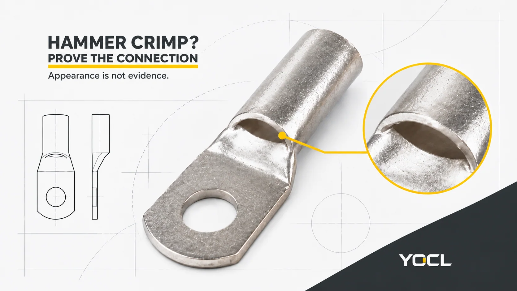
An undocumented hammer crimp is not enough evidence to accept a battery starter or inverter connection. A deep dent can hold the cable while leaving the electrical interface uncertain. If you cannot establish the lug, conductor, tool instructions and verification history, the practical recommendation is to cut off the questionable lug and remake it with a fresh lug and a documented tool combination.
That is a verdict on an unsupported connection, not a claim that every hammer-operated tool or every indent crimp fails. The useful question is whether the process produces repeatable compression and whether the evidence supports this application. Below is a proof sequence: inspect the uncovered joint, pull-test representative samples, examine a sacrificial section where justified, and obtain a professional assessment under service load.
What a crimp must achieve, beyond making a dent
A lug must grip the conductor and provide a stable electrical interface. Compression brings the barrel and strands into intimate contact, consolidates the bundle within the intended crimp zones and limits pathways for contamination at the contacting surfaces. Retention matters because cable movement must not pull that interface apart.
Caltrans’ equipment wiring guidance describes gas-tight connections and requires the connector manufacturer’s application specification and recommended tooling. That is a useful engineering principle, with an important scope limit: its equipment requirements are not a universal battery-lug certification. A visible dent does not demonstrate gas-tightness. Caltrans, Crimps and Terminals
A simple hammer punch loads a local area of the barrel. Without a controlled procedure, the finished deformation can vary with support, alignment, operator and impact. A firm grip at that indentation can coexist with an inadequately consolidated region elsewhere. Conversely, excessive local deformation can damage the barrel or conductor. These are possible failure mechanisms, not a finding that every hammer crimp has the same internal defect.
A matched mechanical or hydraulic system offers a defined relationship between conductor, barrel, forming geometry and completion. It still depends on the correct combination and proper use. Hydraulic power supplies force; it does not decide whether the die fits the lug. Ratcheting action establishes a tool cycle, not automatic suitability for every terminal.
An indent is not automatically a defect
Approved crimp systems can use indent geometry. NASA’s workmanship standard, for example, describes controlled indenter tooling for its own contact applications. Its relevance here is the distinction between a qualified forming process and an arbitrary dent, not permission to apply spacecraft contact settings to battery lugs. NASA-STD-8739.4A, tool controls
Commercial hammer tools also exist specifically for cable connectors. Therefore, neither the word “hammer” nor the outline of an indentation settles acceptance. What an undocumented hammer crimp lacks is a demonstrated process for the exact parts and duty. Hitting harder cannot supply the missing documentation.
What ABYC’s framing actually establishes
The American Boat & Yacht Council’s E-11 addresses AC and DC electrical systems on boats. Its published crimp-tool language connects tool suitability with the required connection performance. The underlying principle is that the tool must be designed for the connector being used and produce the required retention. It is not a universal prohibition on hammer actuation.
There is an access distinction worth preserving. The tool wording is publicly quoted in a Boating interview about ABYC crimp requirements. The numerical examples below were checked against Charlie Wing’s published handbook tables explicitly adapted from E-11. They are historical published guidance, not verification of the latest complete E-11 text. Obtain the applicable edition through the ABYC standards library for an actual acceptance specification.
For a boat installation, a tensile benchmark is only part of the applicable requirements. For a vehicle or stationary inverter installation, citing a marine table does not establish compliance with that system’s requirements. In either case, a passing sample does not certify the lug as a product or prove every installed connection.
The buying implication is practical: ask for the specified connector and conductor combination, tool identification, completion criteria and acceptance evidence. A seller’s statement that a tool “does battery cables” is insufficient to establish all of those items. A tool’s purchase price is equally uninformative.
Can you re-crimp it, and must you redo it?
Can I crimp again over a hammer crimp to fix it?
No: do not improvise a second crimp as a repair. Cut off the questionable lug and remake the termination with a new one. A previously deformed barrel is not the original barrel condition for which the normal tool instructions were established. Another squeeze can conceal the first deformation without demonstrating that the resulting interface is acceptable.
This does not require claiming that every die is physically unable to close around a dented barrel. The problem is that there is no validated rework procedure for the joint in question. Additional forming may further displace or damage material, while the operator has no acceptance basis for the combined result.
Have the cable isolated and verified safe before work. If cutting back leaves insufficient usable conductor or damaged strands, the cable assembly needs reassessment rather than a stretched installation. For the replacement termination, follow the approved process in How to Crimp Cable Lugs; this article does not repeat its preparation and crimp sequence.
Must every hammer crimp be redone?
No evidence supports predicting that every hammer crimp will fail. Equally, “it feels tight” does not establish that an unknown battery connection is acceptable. Separate a documented tool process with traceable checks from an already-covered joint whose construction nobody can establish.
For unsupported battery starter or inverter terminations, the recommendation here is to remake them using a documented lug-conductor-tool combination. Vibration, cable movement and substantial operating load make an uncertain interface consequential. That recommendation does not require waiting for heat damage to appear.
Representative samples can increase confidence in a repeatable process. They cannot retroactively prove that hidden installed joints received the same preparation, alignment or forming. Even in a less consequential application, sample success is evidence for a bounded decision, not blanket permission to ignore the equipment instructions.
Prove your crimp: four checks, with different limits
Visual inspection before heat shrink
Look at the joint while the barrel and conductor entry remain visible. Confirm insertion using the features the particular lug provides; do not demand a sight hole from a design that has none. Check for damaged strands, insulation caught in the contact zone, barrel cracks and deformation inconsistent with the manufacturer’s pattern.
Fins, displaced material or unexpected stretching of the barrel should prompt rejection or technical review against that pattern. Do not assume that a familiar-looking hexagon proves complete compression, or that any change in barrel length is universally forbidden. The intended forming operation changes geometry; unexplained distortion is the concern.
The SC(JGK) peephole copper lug page illustrates an inspection opening for viewing conductor insertion position. That opening does not reveal consolidation throughout the crimp, and its presence is not a performance certificate.
For an existing covered joint, heat shrink is a limitation on inspection, not evidence of good work underneath. Have any necessary exposure or replacement assessed with the circuit safely isolated. Do not cut toward an installed conductor merely to obtain a better view.
Pull testing on representative samples
A firm hand tug is a basic sanity check. It is not a measured tensile test. A meaningful test uses an appropriate fixture and force measurement, the specified loading method and duration, and a recorded result for an identified sample.
The following values are from Wing’s Boatowner’s Illustrated Electrical Handbook, second edition, whose tables are labelled as adapted from ABYC E-11. The accompanying text specifies holding the required load for one minute. These are reference examples, not a complete battery-cable table or confirmation of the current edition. Published E-11 table reproduction, printed pages 106 and 162
| Conductor size, AWG | Published minimum tensile load, lb | Hold duration |
|---|---|---|
| 18 | 10 | One minute |
| 16 | 15 | One minute |
| 14 | 30 | One minute |
| 12 | 35 | One minute |
| 10 | 40 | One minute |
| 8 | 45 | One minute |
| 6 | 50 | One minute |
These rows stop before many battery-cable sizes. Do not extrapolate a load or use the last row for a larger conductor. Obtain the applicable requirement for the actual size and installation, together with the manufacturer’s acceptance procedure.
Samples must represent the same lug, conductor construction, tooling, settings and operator method. Record those identities; otherwise a successful result cannot be related to the work being assessed. A change in barrel construction or cable stranding can invalidate that relationship even when the nominal size remains unchanged.
A pull result establishes mechanical performance under that test. It does not independently demonstrate electrical resistance, environmental durability or the condition of every installed joint. Never substitute body weight, a vehicle or an improvised suspended load for a controlled test. Keep test specimens separate from service assemblies.
Sacrificial cross-section: samples only
Cross-section cutting is for sacrificial samples only, never an in-service joint. It answers an internal-structure question that an exterior photograph cannot. A prepared section can reveal a loose core, uneven strand deformation, damaged barrel material or a mismatch between local indentation and bundle consolidation.
Use a competent inspection service where this evidence is required. Section location and preparation matter: a rough cut can smear metal or disturb strands, making the image misleading. Interpret the section against the acceptance criteria for the actual connector and process, not a generic internet picture.
ECSS high-reliability crimp guidance uses prepared metallographic sections and defined acceptance criteria. Its example shows why “no visible void anywhere” is not a universal rule. Its space-product requirements are not automatically the acceptance specification for a battery lug. Nor can a drawing or photograph alone establish long-term gas-tight performance. ECSS crimp qualification and metallography guidance
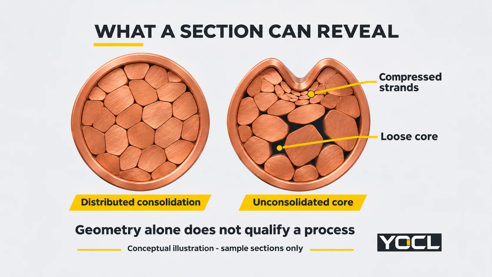
Choose specimens that genuinely represent the proposed work. An excellent section from a different tool or an unusually careful demonstration cannot validate a variable process. Keep the section evidence with the sample identity and pull-test records, while preserving the distinction between process evidence and installed-joint inspection.
Professional load and thermal assessment
For an installed assembly, a qualified person can evaluate operation under an appropriate representative load and compare thermal behaviour with the surrounding connection and cable. This is not an instruction to energize a suspect battery circuit as a DIY experiment. Visible damage or a failed earlier check calls for correction before operation.
A lug appearing hotter than adjacent cable is a reason to investigate, not a universal temperature-based verdict. Surface finish, emissivity, heat conducted from nearby equipment and operating conditions affect thermal observations. A thermal camera does not see inside the barrel, and a cool image during a light or brief load does not establish suitability.
Have the assessment recorded with its operating context. If a termination is found defective, isolate and remake it rather than hiding the symptom. The distinction between barrel and equipment-interface problems belongs in Why Do Cable Lug Connections Overheat?, not another diagnostic framework here.
The hydraulic die-mismatch trap
A hydraulic tool can produce an attractive but unsupported crimp. The pump supplies force to the selected forming parts; it cannot recognize an unsuitable cavity, barrel wall or conductor construction. A nominal marking alone does not establish that an AWG-labelled cable and a metric-labelled die are an approved match.
Under-compression may leave the bundle inadequately restrained. Inappropriate tooling can also produce excess material displacement, fins or damaging distortion. Those observations warrant checking the combination; they do not prove that every inexpensive hydraulic set is mislabelled or that price predicts quality.
Before trusting the result, verify the die identification against the lug manufacturer’s tool or die documentation. If that information is unavailable, changing to a tool with more force does not fill the gap. Use How to Match Cable Lugs, Crimp Dies and Conductors for that separate selection task.
What YOCL’s SC(JGA) page can help you check
YOCL’s SC(JGA) copper cable lug page identifies a copper tubular barrel transitioning to a flat mounting palm for copper conductors and equipment terminals. Its table lists 16 models, from JGA-6 to JGA-630, with model-specific D, d, L, B and mounting-hole diameter fields.
Those details help identify the part being discussed. They do not specify an approved hammer process or establish a tool pairing. The public product information is not an ABYC or UL certificate, and the metal’s appearance does not justify adding a finish claim absent from the page.
When asking about a questionable termination, provide the exact lug model, cable identification, tool and die markings, available uncovered photographs and any sample-test records. Use the Cable Lug Size Chart for the separate dimensional lookup. Request the exact application documentation before treating catalogue dimensions as permission to crimp.
FAQ
Is a hammer crimp safe if I cannot pull the cable out?
A hand tug establishes only that the cable resists that unmeasured effort. It does not establish the specified retention or electrical performance. For an undocumented starter or inverter termination, remake it with a fresh lug and a documented tool combination rather than accepting grip alone.
Can a hydraulic crimper repair an existing hammer crimp?
Do not improvise that repair. The barrel is already deformed, and the normal instructions for a fresh lug do not validate another forming operation over it. Cut off the questionable termination and remake it after safe isolation and reassessment of the available conductor.
Does a good pull-test sample prove all my covered lugs?
No. It supports the tested combination and method, within the test’s scope. It cannot establish how every hidden joint was prepared or formed. Keep sample evidence traceable and assess installed connections separately; heat shrink does not substitute for inspection records.
Do I have to buy a hydraulic tool?
Choose documented compatibility and a controlled completed crimp, not a power source. A suitable mechanical tool can be appropriate when specified for the exact parts. Borrowing, renting or commissioning a cable assembly can resolve the budget question without relying on an unsupported hammer crimp.
References
- California Department of Transportation: Crimps and Terminals, equipment-specific application and tool guidance.
- NASA: NASA-STD-8739.4A, Change 3, crimp tool controls; spacecraft workmanship scope.
- Boating: How to Create Proper Terminal Crimps, published interview quoting E-11 tool requirements; not the current complete standard.
- American Boat & Yacht Council: Standards library, source for the applicable E-11 edition.
- Charlie Wing: Boatowner’s Illustrated Electrical Handbook, second edition, 2006, printed pages 106 and 162, E-11-adapted tensile tables and duration.
- ECSS: ECSS-Q-ST-70-26C Rev.1, 2017, with Corrigendum 1, qualification and metallographic assessment in its space-product scope.
- YOCL: SC(JGA) and SC(JGK) product information linked above; catalogue declarations and visible inspection features, not independent performance tests.