
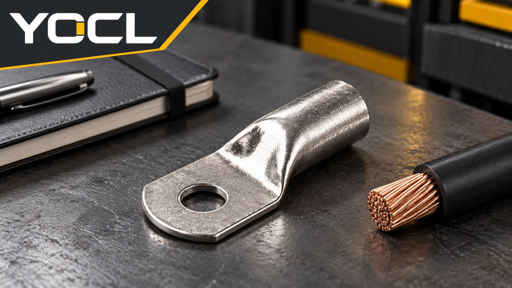
A cable lug connection can overheat when current is excessive for the actual circuit and assembly, resistance increases at the conductor-to-barrel or palm-to-equipment interface, or heat reaches the lug from a nearby component. Damage, contamination, an unsuitable connection or inadequate contact pressure are possible explanations; the hot location alone does not identify which one is responsible.
If there is smoke, a burning smell, arcing, visible scorching, melted insulation or other evidence of damage, stop using the equipment and keep it out of service. Do not touch the connection to judge its temperature or simply tighten it and restart. A competent person should identify and isolate all sources, secure against reconnection and verify the work area is dead before inspection. The UK Health and Safety Executive’s safe working guidance discusses isolation and verifying the work area is dead; its electrical equipment guidance identifies burn marks and staining as warning signs and advises stopping use when safety is in doubt; apply the site’s isolation procedure and local requirements to the equipment concerned.
Start With the Hot Location and the Whole Current Path
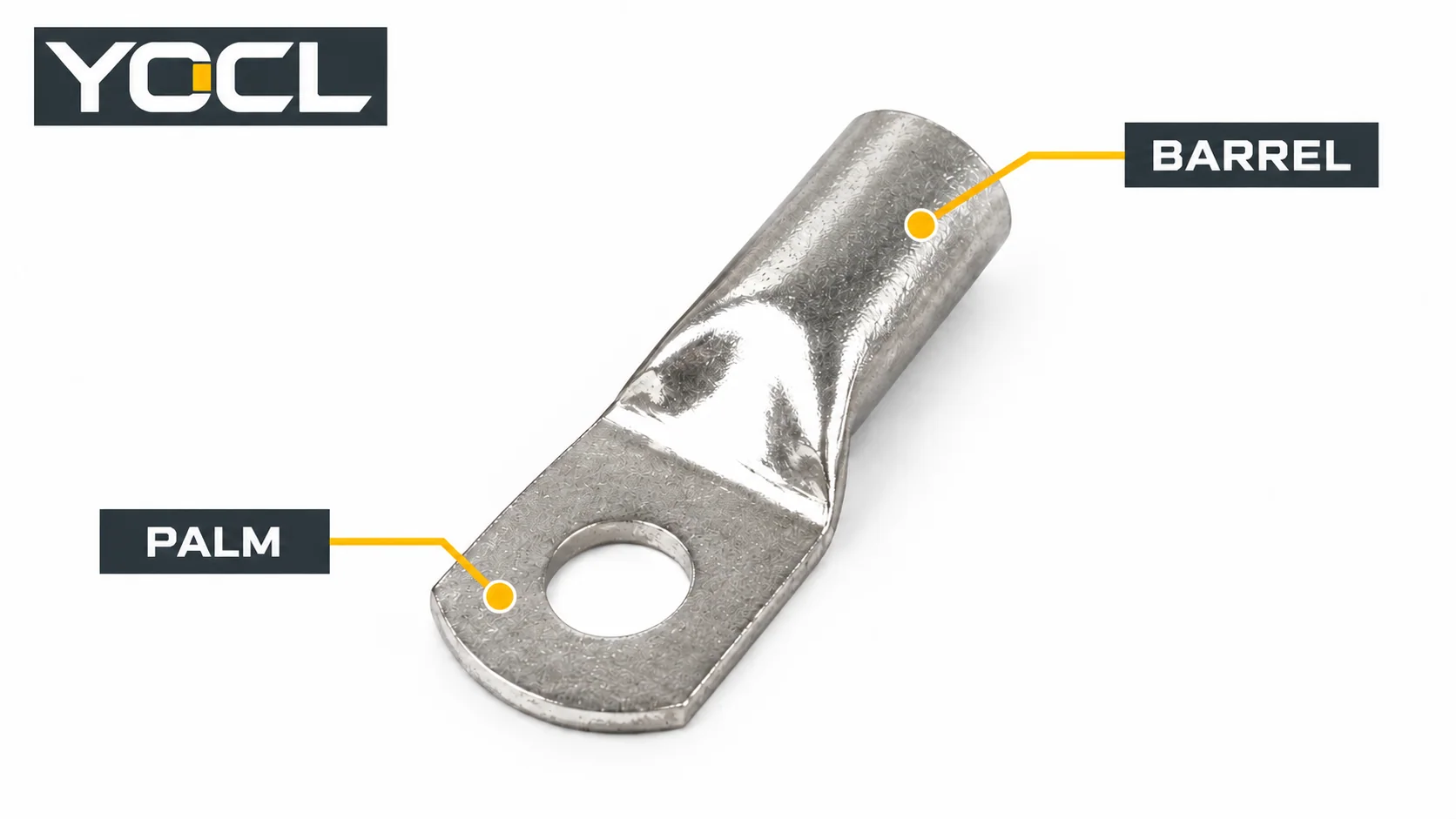
As explained in the cable lug overview, a bolted crimp lug has two distinct interfaces: the barrel grips the conductor, while the palm contacts the equipment terminal or busbar. The conductor, fixing hardware and connected equipment can also carry or transfer heat. One area may look hotter while the cause lies elsewhere.
After safe isolation and verification, document what was observed before disturbing parts: the circuit, lug and conductor identifiers, the apparent hot area, any visible damage, operating conditions and the most recent work on the connection. Use the following table to organize an investigation; none of the observations alone proves a cause.
| Observation | Possible explanation | Safe check after isolation and verification | What to do with the result |
|---|---|---|---|
| Heat or damage appears concentrated at the barrel or cable entry | Conductor-to-barrel contact, damaged strands, an unsuitable crimp or a cable problem | Record the lug and conductor identification, visible crimp condition, conductor condition and available installation records. Avoid destructive testing unless authorized. | Missing or conflicting crimp information needs review against the exact connector, conductor, tool and die documentation; damaged parts need disposition. |
| Heat or discoloration appears at the palm, stud or mating surface | Poor contact, loose or unsuitable hardware, contamination or damage at the bolted interface | Record the hardware and assembly arrangement before disassembly; inspect the mating surfaces under the equipment procedure. | Have the responsible person assess the full joint and any damage. Do not treat retightening as proof of repair. |
| The conductor and several nearby components are warm | Load, ambient heat, a nearby heat source or a broader current-path issue | Review recorded current, duty, protective-device and equipment data, cable route and surrounding temperature conditions. | Compare the complete installed circuit with the applicable equipment and cable documentation; escalate missing data. |
| One connection differs from comparable connections | A local connection problem is possible, but loading or measurement differences may also explain it | Compare phase, duty, conductor, connection type and observation method before drawing a conclusion. | Use the difference to prioritize investigation, not as an automatic pass/fail limit. |
| Melting, arcing, severe discoloration or recurrent overheating | Connection or adjacent parts may have suffered damage | Keep the equipment isolated. Document affected components and involve the equipment owner or manufacturer. | Determine the condition of the lug, conductor, hardware and equipment terminal; replace or repair only as authorized, then verify the assembly. |
Check the Conductor-to-Barrel Interface
Heat at the cable entry directs attention to the crimped connection and conductor, but it does not prove that the crimp alone is defective. A lug may have been used with an incompatible conductor, die or tool, or a conductor may have been damaged before or after assembly. Examine the records alongside the isolated connection: part numbers, conductor material and size, tool and die identification, and any required process or inspection records.
Look for visible damage or evidence that the connection has moved, while recognizing the limits of an exterior inspection. A neat-looking barrel does not establish the condition of every strand or prove a sound crimp. Conversely, a surface mark is not enough to identify the original process or its adequacy. If the evidence is incomplete, obtain the exact manufacturer’s instructions and refer the assembly for assessment. Do not add another crimp or reuse a heat-damaged lug merely because it appears mechanically secure.
For the selection and process-document questions behind this check, see how to match cable lugs, crimp dies and conductors. The cable lug size chart guide explains why conductor and stud interfaces must be checked separately. These guides do not certify the connection being investigated.
Check the Palm and Equipment Contact
The lug palm is part of a bolted contact assembly, not an isolated component. The contact surface, stud or bolt, washers, nut, equipment terminal and their arrangement all matter. After isolation, record the original configuration before disturbing it so that a missing part, an incorrect stack or signs of movement can be investigated.
A loose or damaged interface can increase electrical resistance. NASA’s 1998 Lessons Learned record 1229 describes one specific contactor connection where a loose nut-and-bolt joint overheated under high current; the lugged wires and hardware were damaged, the contactor was replaced and the wires were re-terminated. It is a documented example of one failure, not evidence that every hot lug has a loose nut or that a YOCL product was involved.
For an actual repair, compare the lug, equipment terminal and hardware with the relevant manufacturer’s instructions. Follow the specified contact preparation, hardware arrangement and tightening method for that assembly. A generic torque number, a larger washer chosen by appearance, or tightening an already damaged joint cannot establish suitability. If the palm, mating surface or equipment terminal shows heat damage, the responsible person must decide whether each affected part remains acceptable under the equipment procedure.
Check Load, Materials and the Surroundings
The current and duty seen by a connection matter as much as its appearance. Review the available load record, duration, circuit configuration and protective-device coordination against the applicable equipment, conductor and connector documentation. Consider the entire current path, including upstream and downstream connections. A lug that carries heat from a neighboring component requires a different correction from an isolated poor contact.
Material compatibility is another documented check. Confirm the conductor material, lug designation and equipment interface rather than assuming that similar-looking lugs are interchangeable. Where aluminium and copper interfaces are involved, use the designated connector and manufacturer’s preparation requirements; the copper, aluminium and bimetallic lug comparison explains the different interface roles. Corrosion or contamination is a reason to investigate the environment and interface, not a reason to apply an unspecified compound.
Ambient temperature, restricted heat dissipation and nearby hot equipment can change the thermal conditions of the assembly. Record them with the load and installation details. An individual component’s published rating does not, by itself, prove that the complete installation is suitable under those conditions.
What a Temperature Reading Can and Cannot Tell You
A thermal observation can help locate a difference, but a single reading does not identify the failed interface or prove that a connection is safe. NASA’s thermography overview lists loose connections, failing components and installation problems among conditions that hotspots can indicate. Interpretation also depends on how the observation was made and on the load and surroundings.
Keep the image or reading with its date, location, instrument and method, load, ambient conditions and relevant comparable points if available. Reflective metal surfaces and obstructed views can affect an infrared observation; interpret it with a qualified thermographer and the instrument procedure. Do not open energized equipment, remove covers or take measurements solely because an article suggests a thermal comparison. Any energized assessment must follow the site’s separately authorized safety process.
There is no single universal surface-temperature or temperature-difference limit in this guide. Do not convert a standard’s controlled test condition into an on-site acceptance threshold without the applicable procedure and equipment-specific criteria.
Decide the Next Action and Record It
Before work is closed, the responsible person should be able to answer these questions:
- Where was the abnormal condition observed? Record the barrel, palm, adjacent conductor or equipment location and preserve photographs where safe.
- What evidence supports the suspected cause? Record part and conductor identifiers, circuit conditions, inspection findings and the relevant document revisions. Separate a confirmed finding from a hypothesis.
- What else may be affected? Assess the conductor, lug, hardware, insulation and mating equipment terminal—not just the visibly hottest item.
- What correction is authorized? Use the equipment owner’s change process and the applicable connector and equipment instructions. Replace or repair damaged components as directed; do not restore a damaged assembly by retightening alone.
- How will the result be verified? Complete the required inspections and tests for the equipment and installation, record the results, and allow only authorized personnel to restore it under the site’s procedure. If the cause or integrity remains uncertain, keep it out of service and escalate.
If replacement parts need to be identified, the YOCL cable lug range can be reviewed with the conductor material and size, equipment interface, existing part identification and applicable project requirements. YOCL’s SC/JGA product information identifies a copper cable lug family; its photograph is used here only to illustrate exterior inspection locations, not to establish a fault or approve a replacement.
Related reading: See industrial plug and socket heat diagnosis.
References
- UK Health and Safety Executive, Electricity at Work: Safe Working Practices (HSG85), paragraphs 53–59, safe isolation and precautions near live parts.
- UK Health and Safety Executive, Work Using Electrically Powered Equipment, condition checks and response to suspected unsafe equipment.
- NASA Johnson Space Center, High Electrical Resistance from Loose Connectors, Lesson 1229, 10 December 1998, specific contactor event.
- NASA White Sands Test Facility, Thermography, examples of conditions indicated by hotspots.
- YOCL ELECTRIC, SC/JGA Copper Cable Lugs, product information and exterior image reference.