
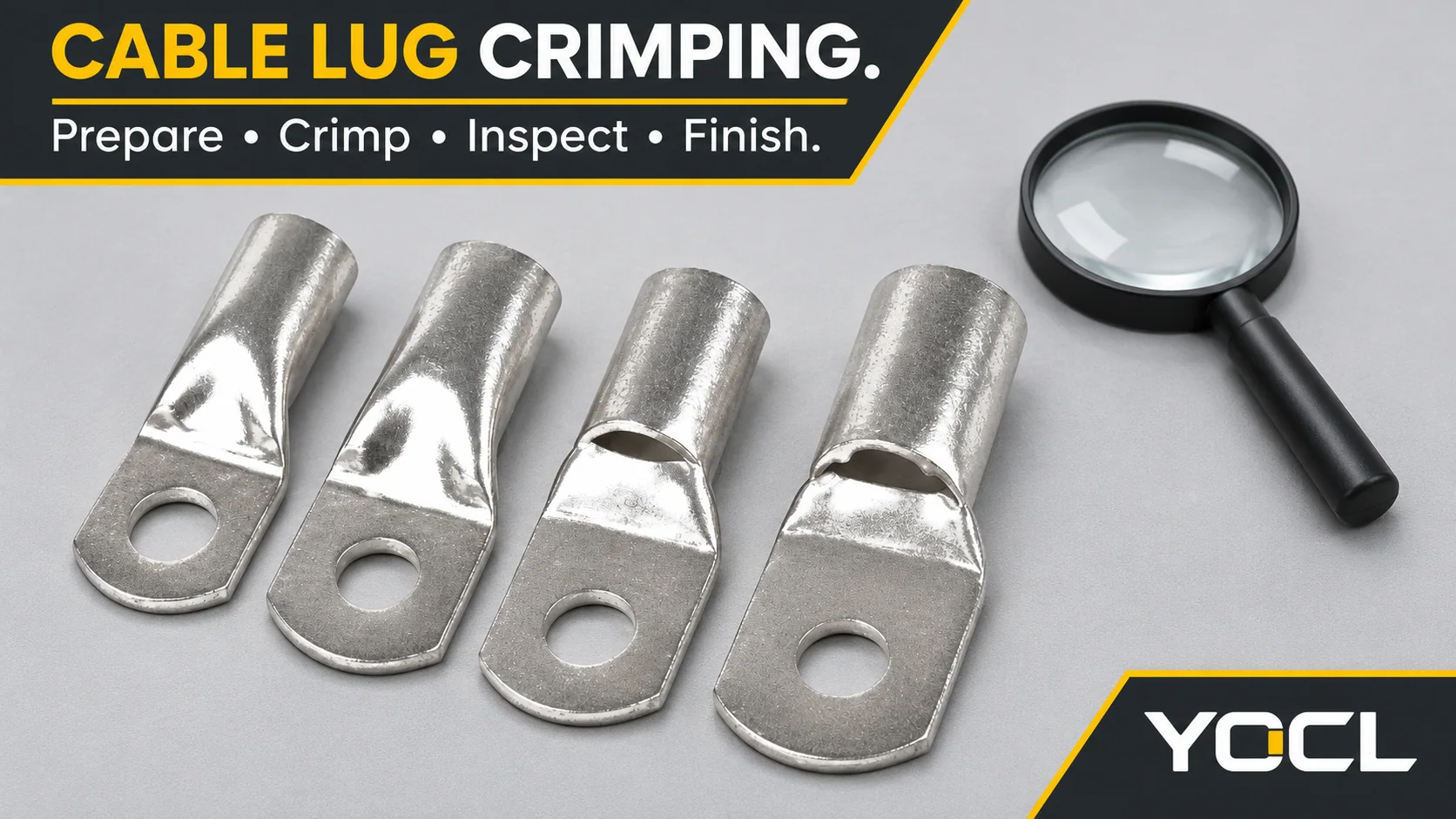
To crimp a cable lug, prepare the specified stripped length, seat the complete conductor in the barrel, make every prescribed compression in its documented order, and complete each tool cycle. Inspect the exposed termination before deburring and insulating it. A finished-looking crimp is not an acceptance result: insertion evidence, process completion and any required mechanical checks must agree.
This procedure starts with an already approved lug–conductor–tool combination. Resolve that prerequisite in How to Match Cable Lugs, Crimp Dies and Conductors; use the Cable Lug Size Chart for dimensional selection. The steps below concern compression cable lugs, not wire ferrules or mechanical screw lugs.
Work on installed cables belongs to qualified personnel under the applicable isolation procedure. Isolate all relevant supplies, prevent reconnection and verify the deenergized condition before handling the conductor. In U.S. workplaces, these duties are addressed by OSHA 1910.333. This is not an energized-work procedure or a complete medium-voltage termination instruction.
1. Prepare the conductor and locate it in the barrel
Set the strip length before cutting
Put the applicable installation instruction beside the workpiece. Identify its strip length, insertion depth and permitted insulation-to-barrel gap as separate checks. Do not substitute the lug’s overall length, palm length or an estimated barrel length for the strip dimension.
Europacable’s medium-voltage accessory guide explains that insulation removal must permit full conductor insertion, with any gap determined by the installation instruction. It also calls for clean conductor surfaces and preservation of supplied interface compound. These are preparation principles, not dimensions for every YOCL lug. Europacable, section 7.1
Measure and mark the required strip position. If the specified sleeve must be parked on the cable before the lug is fitted, put it on now and keep it away from the working area. Strip with a tool suitable for the cable; examine the entire exposed end before inserting it. Caltrans’ equipment wiring requirements call for undamaged conductors and manufacturer-specified strip lengths; their scope is Caltrans equipment, rather than a universal installation code. Caltrans, sections 1.2.4 and 2.2.1
Hold point: if stripping leaves cut strands, visible conductor damage or a damaged insulation edge, resolve the defect before crimping. Do not conceal it inside the barrel. Repreparing the end must still leave enough cable for the intended routing and support.
Gather the strands and prove insertion
Keep the strand bundle together in its intended lay. Guide the whole bundle into the barrel; do not cut away strands to make it enter, fold spare strands back, or add filler. For aluminium or a prefilled barrel, follow the specified surface-preparation and compound procedure rather than improvising a copper-lug cleaning method.
Use this insertion check before the tool grips the barrel:
- Align the cable and barrel. Support the cable so its weight does not pull the end out while the tool is positioned.
- Insert to the documented endpoint. Check for trapped insulation, stray strands at the entry and a conductor that has stopped short.
- Confirm depth by the specified method. Where the design provides an inspection opening for that purpose, inspect it. Where it does not, use the instruction’s insertion reference or approved witness-mark method. Never drill an inspection hole.
- Set palm orientation. Arrange the palm for its intended equipment connection before compression locks its position. Do not plan to correct orientation by twisting the completed crimp.
A reference mark is useful only when its position comes from the actual insertion requirement. An arbitrary mark beside the barrel does not prove that the conductor reached the required depth. If the depth cannot be established, keep the termination on hold.
These checks implement a basic connection requirement: the conductor must be secured without damage. OSHA 1910.303(c) states that requirement for its U.S. workplace scope; it does not supply a lug-specific insertion dimension.
2. Execute the specified crimp positions, count and sequence
Make the crimp map explicit
Before operating the tool, identify each required compression position on the manufacturer’s drawing or work instruction. Locate the first position on the actual barrel and read the remaining positions in order. Count completed compression locations, not handle strokes or hydraulic pump strokes. Several pump strokes may belong to one tool cycle at one location.
Record the job’s sequence in this compact form:
First position: ___ · Next positions, in order: ___ · Total required locations: ___ · Permitted spacing/overlap: ___ · Full-cycle completion indication: ___
Use this as a transcription of the approved process, not as a way to design one. A long barrel does not tell you the crimp count. Do not place an extra compression in every remaining smooth area or overlap impressions unless the instruction specifies it.
There is no safe universal direction rule. Europacable distinguishes hexagonal connector compression progressing outward from the centre from deep-indent compression progressing inward from an end. Its section 7.2 also shows a lug with barrel guide marks. Follow the sequence for the actual lug and compression system; do not copy a splice’s map or reverse the arrows from memory. Europacable, section 7.2
For example, if the applicable lug drawing identifies the palm-side barrel position as the first compression and the cable-entry position as the last, follow that order. This conditional example does not establish the direction or count for an unidentified lug.
Complete each tool cycle before moving
Position the barrel at the indicated location and orientation, keeping the die clear of the palm, transition and insulation unless the specific instruction defines otherwise. Recheck insertion before committing to the first compression.
Operate the tool until its prescribed completion condition is reached. On a full-cycle ratchet tool, that means completing the ratchet cycle; on powered or hydraulic tools, use the completion indication stated in that tool’s manual. Do not assume that handles feeling tight, a motor stopping or an audible sound means success. Caltrans explicitly requires full-cycle release for the ratcheting crimp tools covered by its equipment specification. Caltrans, section 2.2.1
Release the tool as instructed, check that the cable has not displaced, then move to the next specified location. Mark each completed position on the job record. A die impression and a recorded complete cycle answer different questions; retain both when required.
Stop if the tool reports an error, fails to complete, or the lug moves out of position. Identify the affected termination and follow the approved recovery or rejection procedure. Do not count an interrupted cycle as complete or add an improvised second squeeze to make the surface look uniform.
3. Inspect the exposed crimp and apply the acceptance criteria
Inspect before heat shrink hides the barrel. The image below locates visible surfaces; it is not an example of an accepted finished crimp.
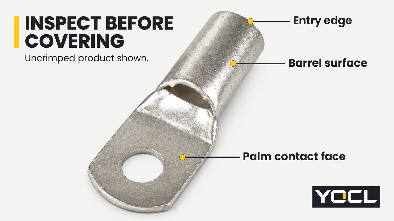
The pictured YOCL SC(JGA) copper cable lugs provide an exterior reference only. For component terminology, see What Is a Cable Lug?.
Use a visible-check and disposition record
The following is an inspection worksheet, not a substitute for the product’s acceptance drawing. Enter the applicable criterion alongside each result.
| Check location or record | What to examine | Hold or reject trigger |
|---|---|---|
| Cable entry | Strand containment, insulation edge and documented gap | Escaped strands, trapped insulation or visible damage |
| Insertion evidence | Required opening, reference mark or recorded insertion check | Evidence of withdrawal, insufficient depth or unresolved depth |
| Compression pattern | Actual locations, count, order record and any required die impression | Missing or misplaced compression; result differs from the approved pattern |
| Tool-cycle record | Completion indication for every required location | Interrupted cycle, error or undocumented recovery |
| Barrel and transition | Cracks, splitting, distortion and sharp projections | Structural damage or shape outside the applicable acceptance criteria |
| Palm and hole | Contact surface and mounting geometry remain serviceable | Damage or distortion that prevents the intended equipment connection |
Do not file away evidence of a split or severely distorted barrel and then mark it acceptable. Separate permitted edge dressing from repair of a defective compression. Missing evidence requires a hold; visible failure against a defined criterion requires rejection or the authorized disposition.
Separate a hand check from a controlled pull test
A manual retention check, if included in the installation procedure, is a screen for obvious movement. A lug that stays attached has not thereby passed a measured tensile test. Conversely, conductor movement or pullout is a reason to stop, not to cover the joint and continue.
Where a project requires a proof-load or tensile test, obtain a complete acceptance instruction before applying force. The inspector needs:
- The exact lug–conductor combination and applicable procedure revision.
- Whether the test is a nondestructive production check or a destructive sample test.
- The required force, application rate or duration, fixture arrangement and permitted movement or failure mode.
- Sampling rules, calibrated measuring equipment, results to record and disposition after failure.
Do not invent a universal force in newtons or kilograms, and do not pull an installed termination to failure as an informal check. A destructive qualification sample and an installed connection serve different purposes.
The official abstract for IEC 61238-1-1:2018 identifies type-test methods and requirements for defined power-cable connectors, including mechanical testing. That scope does not turn a hand tug into a type test or supply a universal site acceptance load. Use the applicable full test procedure and project requirements for numerical criteria.
Release the crimp for finishing only when its visual criteria, process record and required tests are satisfied. Keep any failed or unresolved termination identifiable. If the question instead concerns an existing connection running hot, follow Why Do Cable Lug Connections Overheat for that separate diagnostic task.
4. Remove permitted sharp edges and finish the insulation
After inspection, perform only the edge dressing permitted by the installation process. Europacable’s guide calls for removing sharp points from compressed connectors and cleaning away metal particles. It also emphasizes accurate heat-shrink positioning, controlled heating and cooling before movement. Europacable, sections 7.2 and 9.2
Do not turn deburring into reshaping the barrel, thinning the palm or removing a required identifying impression. Clear debris from the work area and recheck the dressed surface before it disappears beneath insulation.
Position the specified sleeve or boot at the location shown in the termination instructions. Keep insulation and adhesive off the palm’s mating contact area. Use the insulation system required for the voltage, environment and equipment arrangement; a neat black sleeve alone proves neither an insulation rating nor a waterproof seal. OSHA’s U.S. requirements separately address insulation of joints and free conductor ends. OSHA 1910.303(c)(3)
Follow the sleeve’s heating method, recovery temperature and overlap requirements. Inspect the cooled result for incomplete recovery, scorching, splitting, displacement and any specified sealing indication. Do not use heating to disguise a failed crimp, and do not infer a universal heating time from sleeve colour or cable size.
Retain the inspection record before covering: termination identity, instruction revision, completed crimp locations, tool result, required test result and final insulation check. The next handoff is equipment installation and its required verification; completing this lug procedure alone does not authorize energization.
Related reading: See crimping wire ferrules, ring and spade terminal selection and China supplier factory audit checklist.
References
- OSHA — 29 CFR 1910.333: Selection and use of work practices, U.S. deenergization and verification provisions.
- Europacable — Best Practice for the Installation of Medium Voltage Cable Accessories, sections 7.1, 7.2 and 9.2; industry-association guidance within its stated MV scope.
- Caltrans, Division of Equipment — Electrical requirements, sections 1.2.4 and 2.2.1; equipment-specific workmanship guidance.
- OSHA — 29 CFR 1910.303: General, connection and insulation provisions in paragraph (c), U.S. scope.
- YOCL ELECTRIC — SC(JGA) Copper Cable Lugs, first-party product information and exterior photograph used for illustration.
- IEC — IEC 61238-1-1:2018, official public abstract; cited for type-test scope only, not numerical acceptance limits from the full standard.