
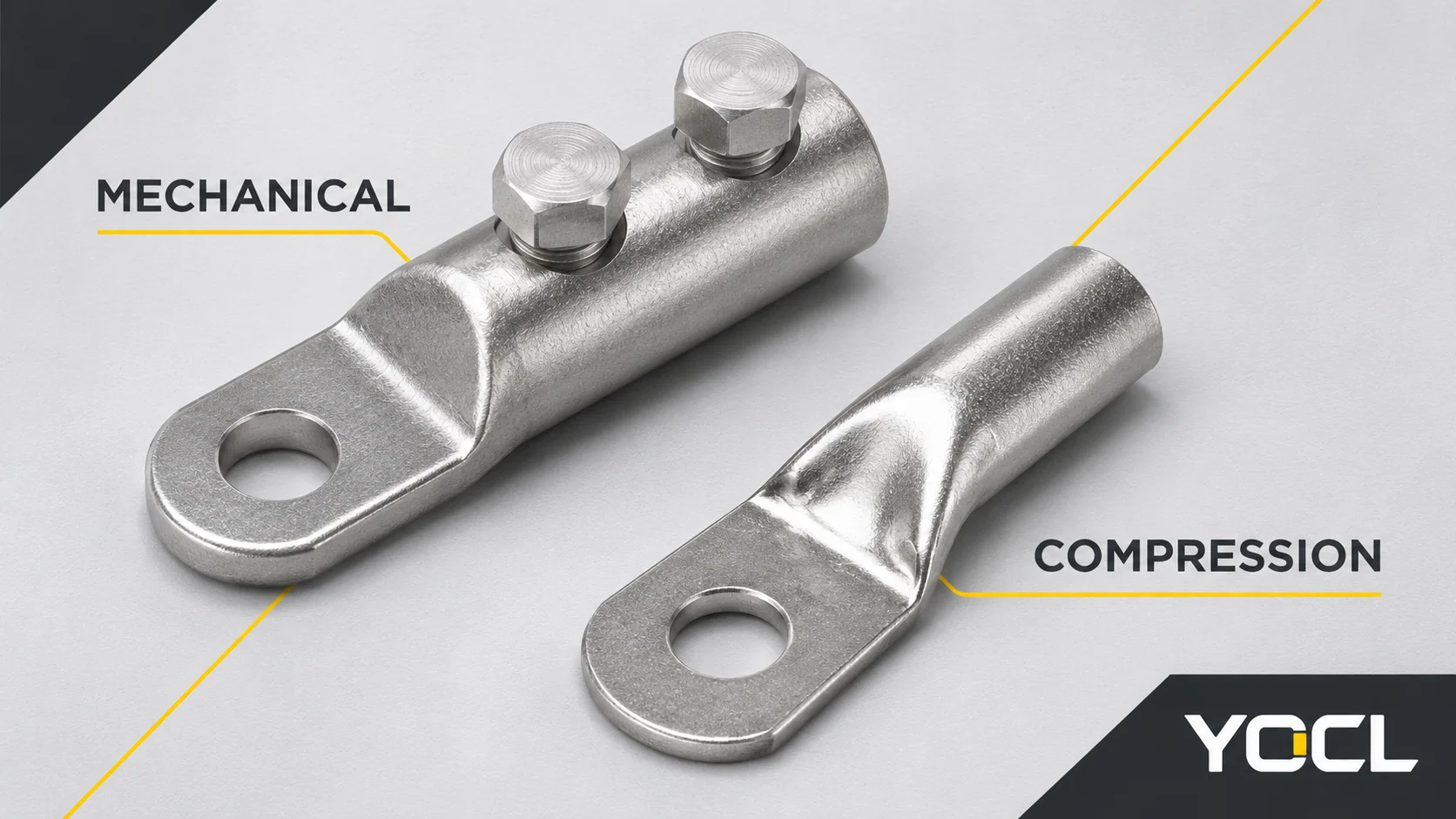
Mechanical cable lugs secure the conductor with screws or bolts; compression cable lugs use a specified crimping process to deform the barrel around it. Choose between them by matching the conductor, equipment terminal and installation process—not by assuming that one method is always stronger, cheaper or easier to maintain.
A mechanical lug is a candidate when the exact connector accepts the conductor and its bolted installation can be completed as specified. A compression lug is a candidate when a documented conductor–lug–tool combination is available and fits the equipment. If either compatibility or the required process is missing, that candidate is not ready to select.
For component terminology, see what a cable lug connects. This comparison addresses the choice of conductor-connection method, rather than a complete installation procedure.
Mechanical vs Compression Lugs at a Glance
| Selection question | Mechanical cable lug | Compression cable lug |
|---|---|---|
| How is the conductor secured? | A screw or bolt arrangement secures it in the connector body. Set-screw and shear-bolt designs require different instructions. | A specified tool/process compresses the barrel around the accepted conductor. |
| What must the installer have? | The selected model’s preparation, bolt and tool instructions; access to perform that procedure. | The documented tool and die combination where applicable, preparation requirements and crimping instructions. |
| How is conductor fit established? | Match material, size range and conductor construction to the model’s acceptance data. | Match the conductor to the exact lug series and approved connection process; barrel fit alone is insufficient. |
| What installation space matters? | Space for the body, projecting bolt heads and the required tool access. | Space for the lug and the specified crimping arrangement, plus equipment-side fastening access. |
| When does the method become a useful option? | The required bolted process is available and the complete connection is suitable, including where a matching crimp system is unavailable. | The required compression system is available, documented and suitable for the proposed connection. |
| What is not established by the method name? | Universal conductor compatibility, reuse permission, or freedom from installation tools. | Universal die compatibility, superior reliability, or suitability for every cable with the same nominal area. |
This table compares selection requirements. It is not a test ranking of the two methods.
Separate the Conductor Connection from the Equipment Connection
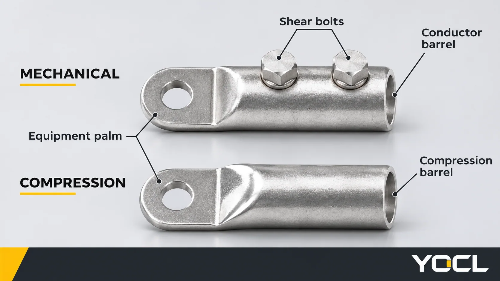
A lug with a mounting palm has two distinct interfaces:
- Conductor side: the cable enters the barrel and is secured by the specified mechanical or compression process.
- Equipment side: the palm meets the equipment terminal or busbar using the specified mounting arrangement.
Both a mechanical lug and a compression lug can have a bolted equipment palm. The presence of a mounting bolt therefore does not tell you how the conductor is secured. Conversely, choosing a compression barrel does not remove the equipment-side fastening requirements.
YOCL’s BLMT shear-bolt terminals illustrate the mechanical form: bolts secure the conductor in the barrel, and a single-hole palm provides the equipment connection. Its SC(JGA) copper lugs show the tubular-barrel and flat-palm form without conductor-clamping bolts. These are construction examples, not interchangeable parts.
For maintenance planning, specify which interface must be disconnected. Removing a lug palm from equipment is a different task from removing the conductor from its barrel. Neither is an energized disconnection procedure; follow the equipment’s isolation and service instructions.
Start with the Conductor, Not the Lug’s Body Material
Record the conductor material, nominal cross-section, construction and cable identification. Then determine whether each candidate accepts that conductor. Fine-stranded, compact and other constructions should be checked against explicit acceptance information rather than treated as equivalent because their nominal areas match.
An aluminium-alloy lug body is not, by itself, proof that the lug accepts every aluminium or copper conductor. Likewise, a model suffix or a bore diameter does not establish the complete connection specification.
In the U.S. workplace context, OSHA 1910.303(c)(1) requires connectors to be identified for the conductor material and properly used. This supports checking the actual identification; it is not a declaration that a YOCL product has a particular approval. For the separate material-selection question, use the copper, aluminium and bimetallic lug comparison.
A real catalogue example: what the BLMT range does—and does not—answer
The current YOCL BLMT table lists the following for BLMT-25/95-13:
| Published field | Catalogue value | What the buyer can check |
|---|---|---|
| Conductor range | 25–95 mm² | Whether the nominal conductor area falls inside the listed range |
| Palm mounting-hole diameter, Φ | 13 mm | The hole dimension against the equipment drawing |
| Overall length, L | 75 mm | The lug’s overall envelope against available space |
| Conductor-clamping bolt quantity | 1 | The selected model’s construction; this does not establish a bolt sequence or torque |
These are manufacturer-declared values from the BLMT product table, not independent test results.
For an illustrative 70 mm² conductor, 70 falls within the listed 25–95 mm² range. That makes the model worth checking further; it does not finish the selection. The conductor’s material and construction, equipment connection, application ratings and installation instructions must still be compatible. If the equipment drawing does not accept the 13 mm palm-hole arrangement, passing the conductor-area check cannot rescue the choice.
By contrast, the SC(JGA) page lists model dimensions and mounting-hole options, but does not establish a crimp die from the model suffix. Ask for the exact conductor and crimp-system match before treating a similarly named compression lug as an alternative. The cable lug size-chart guide explains the dimensional fields.
Compare the Installation Process You Can Actually Perform
Mechanical: identify the bolt system
Do not group every mechanical lug under one tightening instruction. A set-screw terminal requires its specified tightening procedure. A shear-bolt design requires the instructions for that bolt system, including preparation, tooling and any specified sequence or completion criteria.
YOCL’s BLMT range lists one, two or three bolts depending on model. Its public page does not provide a numerical installation torque. The practical next document is therefore the instruction for the selected BLMT model and conductor, not a generic torque chart or a procedure copied from another manufacturer’s shear-bolt lug.
A missing crimp die can be a reason to investigate a mechanical alternative. It is not a reason to fit an undocumented mechanical lug. The alternative must satisfy the same conductor, equipment and project requirements, and its own tools and procedure must be available.
Compression: match the whole crimping system
A crimping tool already on site is useful only if its documented combination covers the selected lug and conductor. Establish the required die or other tooling configuration, conductor preparation, crimp locations and completion/inspection requirements from the applicable instructions.
The detailed lug, crimp-die and conductor matching guide covers that workflow. For this comparison, the decision is whether that documented process can be carried out for the proposed termination. A tool force rating, similar die shape or cable that fits into the barrel does not answer it.
As an equipment-specific example, UL Solutions’ Deadfront Switchboard Application Guide, under “Terminals,” describes instructions for necessary special tools and identification of terminal assemblies intended for the equipment. Its switchboard context reinforces checking the equipment instructions; it does not approve an arbitrary lug/tool pairing.
Check the Palm and Working Space Before Choosing
Compare the candidate drawings against the equipment connection. Check hole diameter or hole pattern, palm dimensions, overall length, conductor approach and the space needed to assemble and inspect the connection. For a mechanical design, include bolt-head and tool access. For a compression design, determine where the specified crimping operation can be performed and whether the terminated cable can then be positioned as intended.
If a candidate fits the cable but requires an unauthorized change to the equipment terminal, it has not passed the interface check. Refer the mismatch to the equipment designer instead of drilling a different hole or assuming a substitute fastener makes it equivalent.
UL’s switchboard guide also addresses terminal-assembly identification and mounting-hardware requirements. Keep equipment-side fastening instructions separate from conductor-side screw or crimp instructions; one value or completed operation does not establish the other connection.
The IEC 61238-1-1:2018 public scope covers compression and mechanical connectors for power cables within its stated low-voltage and conductor conditions. Inclusion of both methods in the standard is not a ranking, a product certificate or evidence that two specific models are interchangeable. Application claims require evidence for the selected configuration.
Which Method Fits Your Job?
The following are decision scenarios, not reported customer cases or installation approvals.
| Job condition | Decision to investigate | Why it changes the choice |
|---|---|---|
| An existing production process already has a documented lug, conductor and compression-tool combination | Keep that compression candidate unless another requirement excludes it | The connection process is established; changing method introduces a new combination to assess. |
| The required crimp system is unavailable, but a mechanical candidate has compatible conductor/equipment data and an executable installation procedure | Consider the mechanical candidate | It offers a different conductor-connection process without requiring the missing crimp combination. |
| Several cable sizes are involved | Compare the exact model ranges and process requirements for each cable | A mechanical range may cover several nominal sizes, but that does not prove acceptance of every conductor material or construction. |
| A replacement must fit an existing equipment terminal | Start with the equipment’s permitted terminal arrangement | A change of connection method is useful only if the new conductor and palm interfaces both work. |
| Both candidates meet the requirements | Compare actual part, tooling, assembly and inspection costs | A project-specific comparison is possible; the category name alone does not establish the cheaper option. |
| Neither candidate has adequate conductor or installation documentation | Hold the selection | Changing the method does not resolve missing compatibility evidence. |
For a quotation, send the cable identification and conductor details, equipment drawing, required application ratings, available tooling, quantity and the intended connection method. Ask for the exact model, accepted conductor configuration, installation instructions and applicable supporting documents together. Start with the YOCL mechanical lug range or the referenced SC(JGA) product information when identifying candidates.
FAQ
Can a mechanical lug be reused after removing the conductor?
Do not infer reuse permission from the word “mechanical.” Obtain instructions for the exact model, including any permitted replacement parts or retermination conditions. A shear-bolt design should not be treated as a reusable set-screw terminal. YOCL’s public BLMT page does not establish a reuse procedure, so reuse is not claimed here.
Can one lug accept two smaller conductors instead of one larger conductor?
Do not select it by adding the two conductor areas. The connector must be identified for the actual conductor count and combination. In the U.S. workplace context, OSHA 1910.303(c)(2)(ii) specifically requires identification of terminals intended for more than one conductor. A nominal size range alone does not establish that permission.
Related reading: See ring and spade connections.
References
- YOCL ELECTRIC, BLMT Series Aluminum Alloy Shear Bolted Connecting Terminal—first-party construction, model range, dimensions and stated installation-information limits; reviewed November 4, 2026.
- YOCL ELECTRIC, SC(JGA) Copper Cable Lugs—first-party copper-conductor application, exterior geometry, dimensions and mounting-hole options; reviewed November 4, 2026.
- Occupational Safety and Health Administration, 29 CFR 1910.303, (c)(1) and (c)(2)—U.S. workplace requirements for conductor-material identification and terminals for multiple conductors.
- UL Solutions, Deadfront Switchboard Application Guide, “Terminals,” “Tightening torque” and busbar-modification guidance—equipment-specific terminal assemblies, tools and mounting considerations.
- International Electrotechnical Commission, IEC 61238-1-1:2018—public scope for compression and mechanical connectors; full test clauses not consulted.